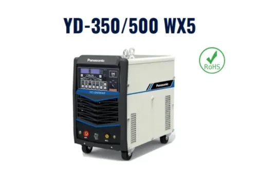

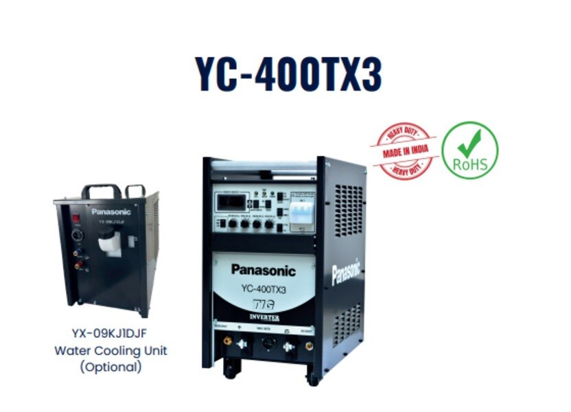
A pulse TIG power source does more than vary amperage: it repeatedly shifts between a high-current peak and a lower background current while controlling arc stability, heat flow and timing. By the end, you will be able to read the pulse cycle, understand TIG inverter operation, choose starting settings and compare a Panasonic source with the rest of your welding setup.
Key takeaways
- Set peak and background current to control heat without changing DC polarity.
- Use pulse frequency and duty cycle to shape arc timing and bead appearance.
- Compare current range, duty cycle, torch rating, gas control and input power together.
- Verify accessories, service support and rental condition before choosing a Panasonic source.
What happens during each pulse cycle
During each cycle, the arc alternates between a high-current peak and a lower-current background level while staying on the same DC polarity. This is the central action of a Panasonic pulse TIG welding power source: it shapes heat delivery without the polarity reversal used by AC TIG.
- Peak current supplies the force that melts the workpiece, establishes penetration and enlarges the weld pool. Raising it can increase penetration and bead width, but excessive peak current causes burn-through or undercut.
- Background current keeps the arc established and maintains enough molten metal for the next peak. Lowering it reduces average heat input and pool size; setting it too low can make the arc unstable or the bead discontinuous.
- Pulse frequency sets how many peak-background cycles occur each second. Low frequency produces visible, widely spaced heat pulses and stronger pool movement; high frequency smooths the arc and creates a more uniform bead.
- Pulse width, also called peak-time percentage, determines how long each cycle remains at peak current. A longer peak period increases penetration and heat input; a shorter one gives the pool more cooling time.
The pulse TIG welding process begins after arc initiation, then repeats these two current levels for as long as the trigger remains active. The background phase does not simply switch the arc off: residual ionisation and the maintained current keep the plasma conductive.
Average current is approximately peak current multiplied by peak-time fraction plus background current multiplied by background-time fraction, but travel speed and joint geometry still control the finished weld.
How the TIG inverter creates and regulates welding current
Incoming AC enters the Panasonic TIG power source and passes through an input rectifier, which converts it into DC on an internal bus. The machine then uses IGBT semiconductor switches to chop that DC at high frequency, rather than relying on a heavy 50 or 60 Hz transformer.
A smaller high-frequency transformer provides isolation and changes the voltage to a welding range. On the secondary side, rectifiers convert the switched output into DC, while the control circuit adjusts switching time to command the selected welding current. This sequence is the core of TIG inverter operation.
A feedback circuit continuously compares actual output with the commanded value. It reacts to changes in arc length, arc voltage and welding load by altering the IGBT switching pattern, keeping current stable as conditions move.
The front-panel amperage is a target, not a guarantee of identical delivered current; duty-cycle limits, thermal protection, cable resistance and remote-control scaling also affect output.
For DC welding of steel, stainless steel, nickel alloys and copper, the torch normally connects negative through DCEN. This places most arc heat in the workpiece and supports penetration. High-frequency start establishes the arc without touching tungsten to the job; lift-arc start uses controlled contact and withdrawal.
During pulse welding, background current does not normally extinguish the arc. It remains above the sustaining level, keeping the shielding-gas path ionised while reducing heat in the pool. That continuous plasma column lets the source return quickly to peak current without repeated starts or tungsten contamination.
How DC pulse TIG differs from steady DC TIG
Pulsing improves thin-section control when a steady DC arc puts too much continuous heat into the joint.
DC pulse TIG welding alternates between a high peak current that melts or advances the pool and a lower background current that maintains the arc while the pool cools; it can reduce burn-through, distortion and heat-affected-zone width without stopping the arc.
Set peak current close to the current you would use for the required travel speed and penetration in steady DCEN TIG.
Set background current high enough to keep the arc stable, usually around 20–40% of peak as a starting point; setting it too low can cause flicker or extinguishing, while setting it too high removes the cooling advantage. Pulse frequency and width then control how long the pool receives heat.
- For thin stainless steel, start with a low pulse frequency, around 1–2 pulses per second, and a 30–50% peak-time ratio. Add filler at the same point in each cycle and adjust travel speed before increasing current.
- For carbon steel, use the same method, but increase peak current or peak-time ratio when the joint needs deeper fusion. Reduce background current only until arc stability begins to suffer.
- For nickel alloys, copper and similar DC-TIG materials, select settings from the joint’s conductivity and thickness rather than copying steel values.
The pulse TIG welding process does not replace consistent torch movement or filler timing. It also differs from AC TIG: DC keeps the polarity fixed, normally with the tungsten negative, while AC reverses polarity for oxide control on aluminium and magnesium.
How to match the power source to the complete welding setup
Match the source to the weld’s thermal demand, not its headline amperage. A 200 A panasonic pulse tig welding power source may be unsuitable if its rated duty cycle, input phase, or torch cooling fails your job; a lower-rated unit can suit thin sheet, short welds, and the required DC or AC output.
Choose a Panasonic TIG power source whose rated current exceeds the procedure’s peak current at the required duty cycle. Confirm that the joint, material thickness, tungsten diameter, shielding gas, and torch rating all support that setting.
| Setup | Power-source match | Complete welding setup |
|---|---|---|
| Thin stainless butt joint | DC, peak current within the machine’s high-duty-cycle range, pulse control | DCEN, 1.6 mm tungsten, pure argon, gas lens, air-cooled torch rated above the working current |
| Medium carbon-steel fillet | DC, current capacity above the procedure value, stable remote control | DCEN, 2.4 mm tungsten, argon, torch with cup access for the joint, rating above peak current |
| Thick aluminium corner joint | AC output with sufficient current and duty cycle | 2.4 or 3.2 mm tungsten, argon or an approved argon-helium blend, water-cooled torch, high-current leads and connectors |
Joint access changes torch angle, cup clearance, arc length, and travel speed; a high-amp source cannot correct poor access. Excessive gas flow creates turbulence and porosity, so set flow for the cup and gas lens rather than turning it up blindly.
Treat the front-panel current as a command, not a guarantee. Cable resistance, remote scaling, input voltage, thermal protection, and operation beyond the duty cycle can reduce delivered current.
What to verify before selecting or hiring a Panasonic source
Do not approve a Panasonic TIG power source from the word “pulse” or its maximum amperage. Match the exact model to your supply, material and torch, then read its operating manual before ordering consumables or booking a rental.
| Check | Why it matters | Evidence to request |
|---|---|---|
| AC or DC output | DCEN suits steel, stainless steel, nickel and copper; AC is needed for aluminium oxide cleaning | Model datasheet and manual |
| Rated and maximum TIG current | The front-panel value is commanded current, not guaranteed output outside the duty cycle | Output curve, duty-cycle table and thermal limits |
| Pulse current, frequency and width | These limits determine heat control and bead shape on thin sections | Pulse-setting ranges in the manual |
| HF or lift start | HF avoids tungsten contact; lift start reduces contamination risk compared with touch-starting | Start-method specification |
| Input voltage and phase | A three-phase unit will not run from an unsuitable single-phase supply | Nameplate and installation instructions |
| Remote, torch and cooling connections | An incompatible foot control, connector or water-cooled torch stops the planned setup | Connector diagram and cooling requirements |
Confirm the permitted torch amperage, work-lead connection, shielding-gas arrangement and protection class. Tig inverter operation relies on electronic switching and cooling, so blocked airflow, low supply voltage or a remote-control scaling error can trigger protection or reduce actual current.
For compatible Panasonic equipment, accessories, spare parts or a rental unit, Weld Tech Corporation can check the model documentation and match the source with the required torch and controls before dispatch. Get the manual, connector details and maintenance record with any hired unit.
Related products
 | TIG Inverter Welding Machines Panasonic TIG Inverter Welding Machines Brand Panasonic MODEL YC-400TX3 INPUT SUPPLY 415 + - 10% PHASE/FREQUENCY THREE / 50-60 HZ RATED INPUT CAPACITY 13.9 KVA/13.2 KW RATED OUTPUT CURRENT... View product → |
 | TIG Welding machine Panasonic TIG Welding Machines Model Number 300 TSP Welding Type TIG Welding Voltage 415V, +10% (Input Voltage) Output Current Range 5-300 A Brand Panasonic Frequency 50-60 Hz... View product → |
Frequently asked questions
What happens during each pulse cycle in DC pulse TIG welding?
The power source alternates between a high-current peak and a lower-current background level while maintaining the same DC polarity.
How does a TIG inverter create and regulate welding current?
The inverter converts and switches electrical power at high frequency, then controls output through feedback from the welding circuit.
How does DC pulse TIG differ from steady DC TIG?
Steady DC TIG holds one current level, while DC pulse TIG alternates peak and background current to manage heat delivery.
What should you match when selecting a Panasonic TIG power source?
Match the source to the electrode, torch, gas system, workpiece, current range, duty cycle, input supply and control requirements.
Related product
 | TIG Welding machine IGBT Controlled DC Pulse TIG Welding Power Source Suitable for TIG/MMA Welding Stable current output even at 5 AMP Sheet thickness even 0.5mm weldable Pulse Frequency upto 500 Hz Digital Display of... View product → |