
A rental cable must match the welder’s output, duty cycle, total circuit length and connector system—not just the machine’s maximum amperage. By the end, you will be able to specify cable size and length, calculate voltage drop, compare handling demands and inspect leads before they return to service.
Key takeaways
- Size cable ampacity for actual current and duty cycle, not machine output alone.
- Calculate voltage drop through electrode and work leads at full circuit length.
- Choose the shortest cable that safely reaches the work area.
- Inspect leads, connectors and insulation before every rental return and dispatch.
Match cable ampacity to welding current and duty cycle
A welder’s rated output current is not the cable’s automatic ampacity. Start welding cable selection with the nameplate, then size the complete circuit for its actual thermal load.
1. Record the machine’s maximum output current, output voltage, rated duty cycle and test basis, such as 300 A at 60% duty cycle. A cable that survives intermittent manual metal arc welding may overheat during high-duty-cycle MIG/MAG, submerged-arc or automated welding.
2. Do not assign a universal safe amperage to 35 sq mm, 50 sq mm, 70 sq mm or 95 sq mm industrial welding cable. Ampacity changes with conductor construction and stranding, ambient temperature, installation condition, cable length and duty cycle. Treat these welding cable options as sizes to verify, not current ratings.
3. Require the manufacturer’s table for the exact cable. It must state rated current and duty-cycle basis, maximum operating temperature, insulation temperature rating, voltage rating, conductor stranding and cable standard. For rubber-insulated flexible arc-welding electrode cable, verify IEC 60245-6 and confirm the marking on the jacket.
Match the table to the process, maximum load and complete lead arrangement, including electrode or torch lead and work-return lead. A short, loosely laid MMA circuit has a different heat demand from a long, heavily loaded automated circuit.
Reject any selection based only on cross-section; use the manufacturer’s stated rating at the required duty cycle and installation condition.
Calculate voltage drop across the complete welding circuit
Treat the complete welding circuit as the electrode or torch lead plus the work-return lead. A 50 ft machine-to-work distance therefore represents about 100 ft of copper when both leads are 50 ft long. For rental welding cable selection, calculate Vdrop = I × R, with R = ρL/A.
| Length or condition | Calculation or comparison | Planning meaning |
|---|---|---|
| 50 ft to the work | 50 ft electrode lead + 50 ft return = 100 ft circuit | Do not calculate drop from one lead alone |
| 300 A, 20 m + 20 m leads | L = 40 m; ρ = 0.0175 Ω·mm²/m at 20°C | Use the full copper path |
| Two 50 mm² conductors | R = 0.0175 × 40 ÷ 50 = about 0.014 Ω | At 300 A, Vdrop is about 4.2 V |
That 4.2 V figure applies before temperature effects. As the cable heats, its resistance rises and the voltage loss increases, which can affect arc performance and machine regulation. Compare the calculated drop with the welding power source’s output range and the process requirement.
Include connector, lug and work-return resistance in a detailed assessment. A loose or oxidised lug can waste more voltage locally than a short length of sound copper. If the loss exceeds the selected limit, upsize the conductor or shorten the run; do not promise that a larger cable always solves every fault.
State the permitted voltage-drop limit in the rental specification, alongside the test current and circuit length. That gives technicians a pass/fail value instead of an assumption.
Choose a length that reaches the work without becoming a hazard
Measure the actual route from the power source to the torch or electrode holder and back to the workpiece. Add enough slack for movement around fixtures, but avoid tight bends at either connector. Select the shortest length that permits safe positioning.
For welding cable for rental services, issue several standard lengths rather than one oversized lead for every site. Extra cable increases resistance, voltage drop, weight, storage volume and abrasion exposure.
- Keep leads away from vehicle routes, sharp plate edges, hot work and standing water.
- Lay high-current cable out during operation; a tightly wound pile sheds heat poorly.
- Confirm the complete electrode-plus-return circuit remains within its voltage-drop and thermal limits.
- Compare cable construction, not just cross-section. Square millimetres do not state outside diameter, mass, flexibility or minimum bend radius.
Request these figures from the same manufacturer for each welding cable option:
| Option | Finished outside diameter | Mass per metre | Minimum bend radius | Recommended storage coil diameter |
|---|---|---|---|---|
| 35 sq mm | Manufacturer datasheet | Manufacturer datasheet | Manufacturer datasheet | Manufacturer datasheet |
| 50 sq mm | Manufacturer datasheet | Manufacturer datasheet | Manufacturer datasheet | Manufacturer datasheet |
| 70 sq mm | Manufacturer datasheet | Manufacturer datasheet | Manufacturer datasheet | Manufacturer datasheet |
| 95 sq mm | Manufacturer datasheet | Manufacturer datasheet | Manufacturer datasheet | Manufacturer datasheet |
A larger conductor reduces electrical loss but increases deployment effort and connector size. Do not substitute a guessed dimension for a manufacturer’s figure.
Specify the lead, connector and machine interface as one system
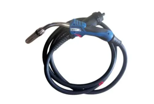
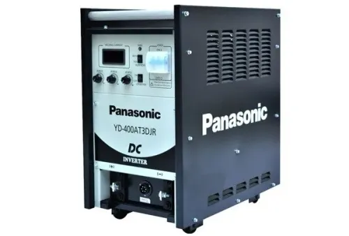
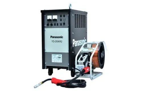
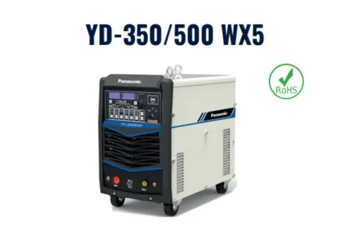
A cable cross-section cannot prove compatibility with a Panasonic or other welding machine. Welding cable for rental services must be specified as a complete lead, connector and machine-interface system.
1. Identify the lead: TIG torch lead, MIG/MAG torch lead, electrode lead, work-return lead or power interconnection. Each may need different terminals, shielding, control conductors, gas or coolant passages and torch-specific fittings.
2. Match the interface to the machine. Check terminal size, lug-hole diameter, barrel dimensions, DINSE-style plug-and-socket size, current class, locking action, contact condition and strain relief. A connector that fits mechanically can still be undersized for the current or duty cycle.
3. Treat polarity as a marking issue for single-conductor industrial welding cable, not as a reason to buy a different copper cable type. The same correctly rated lead can normally serve electrode-positive or electrode-negative welding. Mark electrode and work leads clearly because reversing them changes the welding process.
4. Confirm every connection before issuing the kit: torch to lead, lead to machine, work clamp to return lead, and accessories such as gas hoses, control plugs, coolant lines and consumables. A rental package is incomplete if the torch fitting or clamp does not match, even when the conductor size is correct.
Weld Tech Corporation can check the cable, Panasonic interface, torch, work clamp and consumable package together, preventing a conductor-size-only order that fails at the machine.
Related product
 | Welding Cables Brand Panasonic Usage / Application Industrial Wire Material Copper / Copper Alloy Size 35 sq mm, 50 sq mm, 70 sq mm, 95 sq mm Country of Origin Made... View product → |
Build inspection and replacement rules into every rental cycle
A return-to-service inspection is the control that protects the next user, not a quick continuity check. Make it mandatory for every welding cable for rental services before it is issued again.
1. Examine both ends and the full jacket for exposed braid or conductor, cuts, flattened sections, burn marks, hardened or swollen insulation, crushed areas and vehicle-traffic damage. Remove the lead from service when the damage cannot be repaired to the manufacturer’s method.
2. Inspect lugs for looseness or discoloration, connector bodies for overheating, strain reliefs for separation, and work clamps for worn jaws or weak springs. Continuity can pass while insulation remains unsafe or a termination has high resistance.
3. For equipment operated in the United States, apply OSHA’s rule: do not use a cable with a splice within 10 ft (3.05 m) of the electrode holder. Repair or replace damaged insulation and exposed conductors before release.
4. Record the cable identification, cross-section, length, connector type, inspection date and repair history. Store leads in broad, supported coils without crushing them, and keep them separate from mains extension leads. Welding cable is a single-conductor output lead, not a welder input-power cable.
This record makes welding cable selection a repeatable fleet-control process rather than a judgement made at dispatch.
Frequently asked questions
How do you match welding cable ampacity to welding current?
Start with the machine nameplate output, then account for duty cycle, cable length, conductor size and the heat produced during the rental task. Select a cable rated for the actual thermal load rather than treating the machine’s maximum output as automatic cable ampacity.
How do you calculate voltage drop in a welding circuit?
Calculate resistance through the complete circuit, including the electrode lead and work lead, then multiply resistance by welding current. Include both cable lengths, because voltage travels out to the arc and returns through the work lead.
What welding cable length is safest for rental equipment?
Choose the shortest pair of leads that reaches the work without tension, sharp bends, hot surfaces or trip hazards. Excess cable adds voltage drop, handling problems and opportunities for insulation damage.
What should you inspect before renting out welding cables?
Check the insulation for cuts, crushed sections, exposed conductor, burn marks and oil damage. Inspect lugs, connectors, strain reliefs and the machine interface, then remove a lead from service when damage or overheating compromises its rating.