
A weak arc, porous bead, failed high-frequency start, or overheating inverter does not automatically mean the TIG machine is defective. Trace the fault from incoming power and work return through gas, torch, tungsten, settings, and material condition before comparing pulse controls or accepting a demonstration weld.
Key takeaways
- Check power, earth, torch, gas, and tungsten before condemning the power source.
- Match arc symptoms to contamination, gas flow, polarity, setup, or control faults.
- Treat pulse frequency, peak current, and background current as waveform controls.
- Approve a TIG machine only after it passes your real production joint test.
Start with the fault path: power, earth, torch, gas, and tungsten
A defective TIG power source is the last conclusion, not the first: follow this fault path in order during TIG power source troubleshooting.
1. Measure voltage at the machine terminals under load and compare it with the nameplate range. Inspect extension-lead size, loose input terminals, phase connection, breaker capacity, cooling fan, and air intake. Low voltage or restricted cooling can imitate an inverter fault.
2. Clamp the work lead directly to clean parent metal. Then check torch-switch continuity, remote/local selection, 2T or 4T mode, and connector pins. A poor return or failed control connection can look like unstable output or failed high-frequency starting.
3. Confirm that the cylinder is open and contains argon. Set the regulator for the torch and cup, verify that the solenoid opens, and inspect the hose, fittings, torch head, and gas lens for leaks or blockage. A flowmeter reading does not prove gas reaches the tungsten.
4. Remove obstructions from the collet, collet body, cup, and ceramic. After pool or filler contact, grind contaminated tungsten lengthwise; do not grind around its circumference.
5. Set DCEN for steel, stainless steel, nickel, titanium, and most copper work. Electrode-positive rapidly heats the tungsten and can cause melting or inclusions.
6. Clean oil, paint, rust, galvanising, and oxide from the workpiece. Check joint fit-up and close excessive gaps; poor preparation can mimic weak current or an inverter defect.
Match each welding symptom to its likely cause
Unstable arcs, failed starts, porosity, cracking, and poor penetration point to different fault paths. In dc pulse TIG machine problems, separate high-frequency ignition, lift-start, and work-return faults before changing current; this keeps tig power source troubleshooting from becoming guesswork.
1. If HF does not start the arc, test torch-switch operation, remote-control continuity, the selected 2T or 4T program, HF enablement, ignition circuitry, and the HF gap. Check that lift-arc mode was not selected accidentally.
Clamp the work lead to clean parent metal: a poor return can imitate HF failure and cause unstable voltage after ignition.
2. If the arc wanders, inspect tungsten shape, polarity, arc length, torch angle, gas flow, and magnetic effects before raising current. A long arc spreads the arc and reduces shielding at the joint, producing a broad, dull bead.
3. Porosity points to an empty cylinder, a leak, blocked gas passage, incorrect regulator setting, drafts, or turbulent excessive flow. Start argon testing around 7–10 L/min, then adjust for cup diameter, gas lens, joint geometry, and airflow. More gas is not a reliable cure.
4. If the tungsten turns gray or the bead discolours after shutdown, extend post-flow temporarily and inspect the torch, cup, and gas path.
5. Crater cracking requires controlled downslope and filler at the finish. Lack of fusion requires checks of travel speed, joint preparation, arc length, and actual current.
6. Verify thermal trips against current, ambient temperature, fan cleanliness, input conditions, and the stated duty cycle. A shutdown is not automatically an inverter failure.
Read pulse controls as a waveform, not a low-heat button
Peak current establishes the forceful part of each cycle and influences penetration. Background current keeps the arc established while reducing average heating; duty cycle, or peak-time percentage, sets how long the arc stays at peak current, and frequency sets how many cycles occur each second.
| Control | Increasing it does | Failure sign |
|---|---|---|
| Peak current | Sharpens the arc and increases penetration | Thin material overheats or the bead becomes too forceful |
| Background current | Maintains the arc with less heating | Too low causes poor arc response at low amperage |
| Peak-time percentage | Extends peak heating in every cycle | Excessive duty cycle leaves no useful cooling interval |
| Pulse frequency | Increases cycles per second | Too low surges and freezes the puddle; too high hides the pulse effect |
Diagnose these controls together. Raising peak current while shortening peak time can preserve a similar indicated average current yet produce different penetration because resistive heating rises approximately with current squared.
Establish arc length and torch angle first; excessive arc length spreads the arc, reduces shielding at the work surface, and can make a stainless or nickel bead look under-penetrated.
Visible overheating between pulses points to excessive peak current, peak time, slow travel, or inadequate heat sinking, not frequency alone. Return a DC pulse TIG machine to a known program, then compare manual current with a calibrated meter or diagnostic display before condemning the pulse circuit.
On a TIG welding machine, pulse frequency changes DC current cycling; AC frequency changes polarity-cycle rate.
Test the claimed thin-sheet performance against the real joint
A 5 A minimum output suits your work only if the actual joint produces a stable puddle at 5 A. Material, tungsten diameter, cup size, arc length, filler diameter, and travel speed matter more than the headline specification.
A 0.5 mm sheet demonstration can fail on your joint because of a wide gap, poor fit-up, heavy tungsten, oversized filler, excessive arc length, slow travel, or excessive peak-time duty cycle. Set up the test with:
- A small, correctly sharpened tungsten
- DCEN for steel and stainless steel
- A short, consistent arc length
- Clean, tightly fitted edges
- Travel speed that prevents heat accumulation
Many DC pulse TIG machine problems are setup problems rather than inverter faults. Establish the arc and torch position before changing pulse frequency or peak current.
| Machine type | Suitable work | Main advantage | Limitation |
|---|---|---|---|
| DC pulse TIG | Stainless steel, mild steel, carbon steel, copper, nickel | Controls heat and puddle timing | More controls to set and diagnose |
| Non-pulse DC TIG | The same DC materials | Simpler operation and easier servicing | Less control over heat timing |
| AC/DC TIG | Aluminium and magnesium, plus DC metals | Provides the required AC polarity cycle | Costs more than DC-only equipment |
| TIG/MMA combination | TIG work plus stick welding | One power source for two processes | Verify TIG controls, HF start, duty cycle, and low-current stability |
For aluminium or magnesium, choose AC/DC. Switching a DC tig welding machine to electrode-positive is not an aluminium solution; it overheats the tungsten and does not provide proper oxide-cleaning control. Judge the machine on the joint you will weld, not a showroom sheet test.
Use a production acceptance test before choosing the machine
Verify industrial TIG equipment in Pune by reproducing your production job, not by watching a five-minute showroom arc. Test the actual site supply under load, measure voltage at the machine terminals, and run the target current and pulse program until the fan, duty-cycle limit, and thermal shutdown have been tested.
Check each control and interface:
- HF start and accidental lift-arc selection
- Torch-switch and foot-pedal response, including remote/local selection
- 2T/4T behaviour, upslope, downslope, and crater current
- Gas-solenoid timing, pre-flow, and post-flow
- Torch, remote, and connector compatibility
Weld the real stainless steel, mild steel, carbon steel, copper, or aluminium joint using the intended torch, tungsten, cup, filler, and gas flow. Record peak current, background current, pulse frequency, duty cycle, arc length, travel speed, bead appearance, penetration, and tungsten condition.
| Test result | What it proves | Failure consequence |
|---|---|---|
| Stable output at site voltage | Input supply and current delivery suit the installation | Wrong phase, undersized supply, or voltage drop can cause trips |
| Consistent pedal and torch response | Control interfaces command the inverter correctly | A control fault can imitate a defective power source |
| Clean bead and bright tungsten after post-flow | Gas timing and shielding protect the weld | Oxidation can appear after an otherwise good weld |
| No trip during the planned cycle | Duty cycle matches production demand | A short demonstration has hidden overheating |
Ask how replacement torches, collets, ceramic cups, gas lenses, tungstens, remotes, and circuit boards are sourced, and who diagnoses repeat faults. Weld Tech Corporation can match Panasonic equipment and accessories to the supply and support an acceptance test. Choose the machine that passes the complete application test, not the one with the longest control list.
Related products
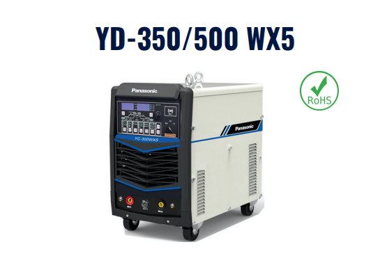 | ac/dc tig welding machine Full Digital AC/DC TIG Welding Machine A variety of waveforms ensures superior welding for aluminum and a wide range of metals. View product → |
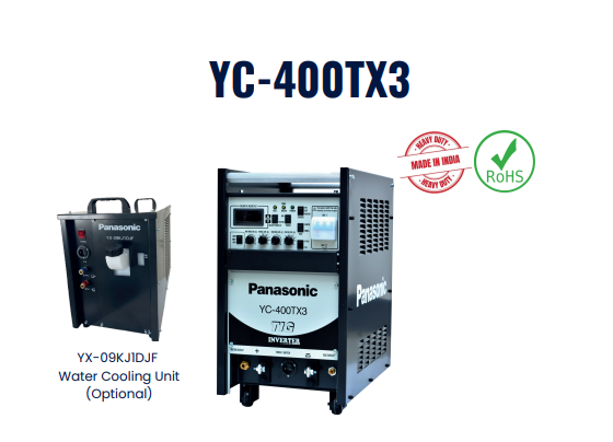 | TIG Welding machine IGBT Controlled DC Pulse TIG Welding Power Source Suitable for TIG/MMA Welding Stable current output even at 5 AMP Sheet thickness even 0.5mm weldable Pulse Frequency upto 500 Hz Digital Display of... View product → |
Frequently asked questions
What should you check first when troubleshooting a DC pulse TIG machine?
Follow the fault path in order: verify input power, earth connection, torch condition, shielding-gas delivery, and tungsten preparation before replacing the power source.
What causes common TIG welding symptoms such as arc instability or contamination?
Likely causes include a poor earth, damaged torch parts, incorrect gas flow, leaks, contaminated tungsten, unsuitable polarity, or incorrect pulse and current settings.
How should you use pulse controls on a TIG welding machine?
Read peak current, background current, pulse frequency, and duty cycle as parts of one waveform. Pulse is not simply a low-heat setting.
How can you test a TIG machine's thin-sheet performance before buying it?
Run the machine on the actual material thickness, joint design, filler metal, tungsten, shielding gas, and travel speed used in production, then inspect the weld.
What belongs in a production acceptance test for industrial TIG equipment?
Record the real joint procedure, arc starts, current stability, pulse response, gas performance, duty cycle, weld appearance, operator adjustments, and repeatability across test welds.
Related products
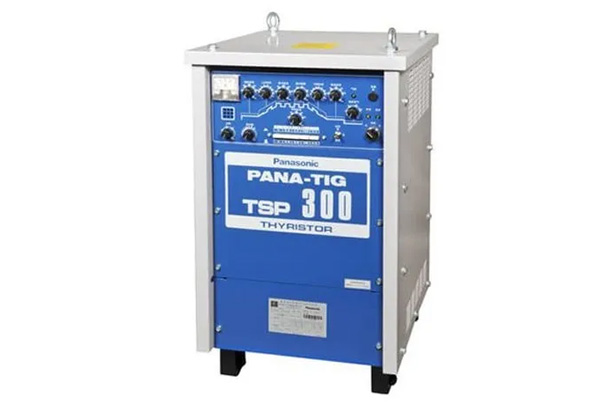 | TIG Welding machine Panasonic TIG Welding Machines Model Number 300 TSP Welding Type TIG Welding Voltage 415V, +10% (Input Voltage) Output Current Range 5-300 A Brand Panasonic Frequency 50-60 Hz... View product → |
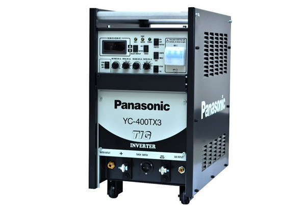 | TIG Inverter Welding Machines Panasonic TIG Inverter Welding Machines Brand Panasonic MODEL YC-400TX3 INPUT SUPPLY 415 + - 10% PHASE/FREQUENCY THREE / 50-60 HZ RATED INPUT CAPACITY 13.9 KVA/13.2 KW RATED OUTPUT CURRENT... View product → |