
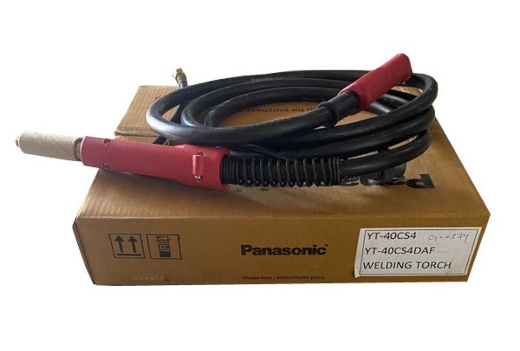
Choosing a Panasonic-compatible wire requires more than matching a diameter or brand name. You will need to verify the wire classification, base metal, shielding gas, spool geometry, feeder components and welding procedure before comparing price or installing a spool.
Key takeaways
- Match wire diameter, classification and shielding gas to the material and transfer mode.
- Confirm feeder liner, contact tip, torch connector and spool dimensions before ordering.
- Compare usable wire, traceability and downtime—not spool price alone.
- Test settings and correct porosity, lack of fusion and burn-through before production.
Match the wire diameter, classification and gas to the job
A 0.8 mm MIG welding wire suits thin-to-moderate mild-steel work, short-circuit transfer, small fillet welds, root passes and out-of-position welding. Choose a larger diameter when thick sections, wide grooves, long welds or high deposition rates make repeated passes inefficient.
A tight root or overhead joint favours 0.8 mm; an open groove or production fillet may favour 1.0 or 1.2 mm.
ER70S-6 is an AWS A5.18 carbon-steel solid-wire classification. Its manganese and silicon deoxidizers tolerate mill scale and light surface contamination, but they do not replace removing oil, paint, heavy rust or galvanized coating.
It is not the correct wire for stainless steel, aluminium or higher-strength steel unless the welding procedure specifically calls for it; Panasonic MIG wire that fits the feeder is not automatically suitable.
| Gas | Arc behaviour | Best use |
|---|---|---|
| 100% CO₂ | More spatter and a narrower setting window, with strong penetration | Cost-sensitive carbon-steel work where cleanup is acceptable |
| Argon with 15–25% CO₂ | Smoother, more stable arc, less spatter and a wider usable window | Cleaner mild-steel welds and appearance-sensitive work |
For clean carbon steel, start with DCEP, 15–20 L/min gas flow, 10–12 mm stick-out, 17–21 V and about 80–140 A. Adjust wire-feed speed to establish current, then tune voltage, feed speed and travel speed on a test coupon for short-circuit, spray or pulsed transfer.
Pulsed transfer requires a machine with suitable pulse controls; these settings are not universal.
Verify the Panasonic feeder and torch before ordering a spool
A correct wire diameter does not guarantee a usable Panasonic MIG wire setup. Verify the complete feeder, torch and spool path before ordering a mig wire spool.
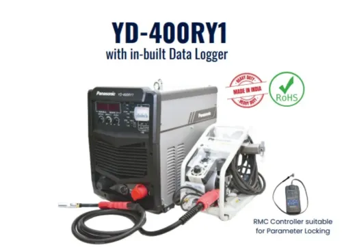
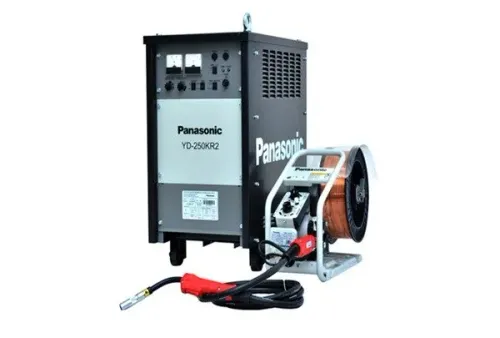
1. Record the exact machine and feeder model, then read its manual for wire-feed speed, current capacity, torch connection, polarity and approved consumables. The Panasonic YD-250KR’s 50–250 A output range describes machine capacity, not a wire specification; select current and feed speed for the wire diameter and joint.
2. Match the spool to the feeder: flange diameter, spool width, arbor-hole diameter and maximum permitted mass. A 15 kg spool can be unusable when its flange or arbor does not fit.
3. Match every guiding part to the wire. Check the drive-roll groove and profile, liner bore and length, and contact-tip bore. Do not run 1.2 mm wire through a 1.0 mm liner or tip; drag and burnback can follow. An oversized drive-roll groove reduces traction and causes slipping.
- For bird-nesting, slipping rolls, burnback or an unstable arc, follow this order:
- Inspect inlet-guide alignment.
- Release excessive spool-brake tension.
- Clean or replace the liner.
- Fit the correct contact tip.
- Set roll pressure only high enough to feed.
- Remove sharp torch bends.
- Confirm DCEP and gas flow.
- Run a controlled coupon with the intended torch and rolls.
“Panasonic-compatible” marketing does not prove compatibility with every manual, robotic or bulk-feed package.
Compare spool quality, traceability and true operating cost
A 15 kg spool is not automatically better than a 5 kg spool: confirm flange diameter, arbor size, spool width, winding direction, cast, helix, package integrity and feeder limits before ordering industrial MIG welding wire. Drums and bulk packages reduce changeovers only when production volume, drum equipment, liner alignment and feeder capacity justify them.
| Package | Check before purchase | Cost or risk |
|---|---|---|
| 5 kg spool | Fits flange, arbor, width and maximum mass limits | More changeovers; useful for low-volume work |
| 15 kg spool | Confirm feeder brake, drive rolls and torch-feed capacity | Fewer changes; unusable if oversized |
| Drum or bulk package | Verify drum equipment, liner length, straight wire entry and alignment | Lowest interruption risk only at suitable production volume |
Compare Panasonic-branded wire with equivalent ER70S-6 by copper-coating consistency, winding quality, feeding behaviour, availability, price and technical support—not brand name alone. Cost per deposited kilogram equals spool cost divided by net wire mass multiplied by deposition efficiency; then add changeover labour, rejected welds, downtime, contact-tip wear and liner wear.
A cheap mig wire spool costs more when it causes feeding interruptions.
Require the label and certificate to state:
- AWS classification, diameter and tolerance
- Lot or heat number and manufacture date
- Coating condition and compliance documents
“ER70S-6” alone provides no full traceability until those records arrive. Keep unopened wire sealed and dry, prevent condensation, and protect the copper coating. Reject rust, wet packaging, flaking coating or contamination.
Tune the process and diagnose defects before releasing production welds
Validate a new mig welding wire, gas and machine combination on a coupon made from the production base metal, with the same joint design and welding position. Record wire diameter, AWS classification, lot number, gas composition and flow, polarity, wire-feed speed, voltage, amperage, stick-out, travel speed, and required preheat or interpass temperature.
Check ventilation, fume exposure, cylinder and regulator setup, work lead grounding, and the finished weld for profile, fusion, cracks, porosity and dimensional acceptance.
- Porosity suggests contaminated steel, moisture, gas leaks, inadequate flow or excessive turbulence.
- Lack of fusion suggests insufficient heat input, excessive travel speed or poor joint preparation.
- Excessive spatter suggests the wrong gas, unstable short-circuit transfer or poor settings.
- Undercut and burn-through point to excessive voltage, excessive current or slow travel.
- Worm tracks indicate shielding-gas or contamination problems.
- An unstable arc points to contact-tip wear, feeding drag, poor winding or incorrect polarity.
| Wire type | Usual polarity | Control |
|---|---|---|
| Solid ER70S-6 | DCEP | AWS A5.18 classification and data sheet |
| Self-shielded flux-cored | DCEN commonly | Exact classification and data sheet |
| Gas-shielded flux-cored | DCEP commonly | Confirm the manufacturer’s instructions |
AWS classification identifies the consumable, not a qualified welding procedure. Where required, qualify the procedure for base-metal group, gas, preheat, interpass temperature, wire size, current, voltage and travel speed. A test coupon exposes problems before an industrial MIG welding wire setup reaches production.
Know when 0.8 mm wire is the wrong purchase and when support matters
A 0.8 mm carbon-steel wire is the wrong purchase when the joint needs more deposition than its feed rate can deliver, or when the base metal and procedure require another wire family.
1. Change diameter or process for thick-section joints where repeated passes with 0.8 mm wire create excessive welding time, heat input or distortion. Heavy production work may justify larger industrial MIG welding wire, a 15 kg spool or a drum, provided the feeder and drum equipment support it.
2. Recheck difficult out-of-position welds. A different diameter, short-circuit transfer or pulsed transfer can provide better puddle control than forcing 0.8 mm wire through an unsuitable setup.
3. Do not substitute when a qualified welding procedure specifies another classification, wire size, gas or transfer mode. Galvanized steel needs controlled coating removal, zinc-specific fume controls and a procedure suited to zinc.
4. Ordinary carbon-steel wire is not suitable for stainless, aluminium or low-alloy steel because a Panasonic feeder accepts the same diameter. Aluminium often needs U-groove rolls, a low-friction liner, a spool gun or push-pull system, and different contact-tip clearance.
Before ordering Panasonic MIG wire, obtain the machine and torch model, feeder setup, liner and consumable details, then request a trial spool and controlled test. Weld Tech Corporation can help with availability, replacement parts, feeder inspection, repairs and parameter advice; judge that support against changeover risk and downtime, not only spool price.
Related product
 | MIG Welding Wires Brand Panasonic Usage / Application MS Welding Thickness 0.8 mm Wire Material Copper / Copper Alloy Grade ER70S-6 Yield Strength Greater-than or... View product → |
Frequently asked questions
When is 0.8 mm MIG welding wire the wrong purchase?
Choose a larger diameter when thick sections, wide grooves, long welds or high deposition rates make repeated passes inefficient.
What should you verify before ordering a Panasonic MIG wire spool?
Check the Panasonic feeder and torch, including liner size, contact tip, connector, drive rolls and spool dimensions.
How do you compare the true cost of an industrial MIG welding wire spool?
Compare wire classification, batch traceability, winding quality, usable wire, feeding reliability, waste and downtime alongside the purchase price.
What should you check before releasing production welds?
Tune wire feed speed, voltage, shielding gas flow and torch position, then diagnose defects such as porosity, lack of fusion and burn-through.