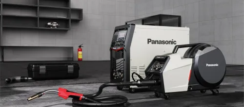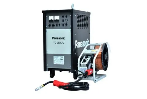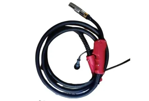

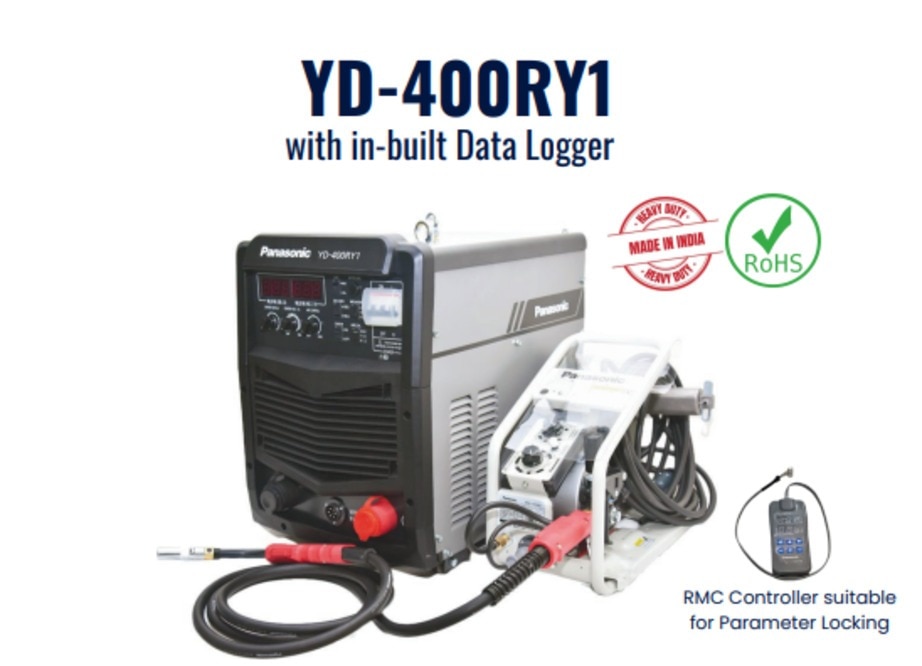
Choose the output, wire system, gas, duty cycle and electrical supply from the weld you must produce—not from the machine’s maximum amperage or an IGBT label. By comparing usable capacity, operating cost, serviceability and acceptance-test results, you can identify a machine that suits your material, production schedule and site conditions.
Key takeaways
- Match 250–500 A output to wire diameter, plate thickness and duty cycle.
- Set gas, wire diameter, polarity and transfer mode as one system.
- Test feeder, torch, input supply and protection separately from the IGBT label.
- Compare consumables, downtime, power use and service before choosing a machine.
Match output current to the wire, plate and production cycle
Choose 250 A, 350 A, 400 A or 500 A from the wire diameter, plate thickness, joint type, transfer mode and shielding gas—not the nameplate maximum. Solid mild-steel wire of 0.8 mm suits lighter fabrication; 1.0 mm and 1.2 mm wire support thicker plate and higher deposition.
Use the wire manufacturer’s procedure chart for starting current and voltage, then account for fillet size, joint access and welds per shift.
| Model | Best fit | Main caution |
|---|---|---|
| 250 A | 0.8 mm wire, light fabrication and short welds | Limited headroom for thick plate or high deposition |
| 350 A | 1.0 mm wire and regular fabrication | Check duty cycle at the required current |
| 400 A | 1.0 or 1.2 mm wire, larger fillets and heavier joints | Occasional 400 A output may not suit production |
| 500 A | 1.2 mm wire, long welds and high deposition | Costs more if the procedure cannot use its capacity |
Read rated output at the intended duty cycle. A 60% rating means six minutes welding and four minutes cooling in a 10-minute period at the stated current and reference temperature; it is not continuous operation.
Compare ratings at identical current and test conditions: 60% at 350 A is not 60% at 250 A. Select headroom for starts, stops and heat, but do not pay for unused output in a CO2 MIG welding machine or industrial MAG welding machine.
Choose gas, wire and starting settings as one welding system
A controllable arc starts with matched gas, wire, polarity and settings. For ordinary solid mild-steel wire, use DCEP (electrode positive) unless the wire manufacturer specifies otherwise. Self-shielded flux-cored wire is a common DCEN exception; the wrong polarity causes unstable transfer, spatter and poor penetration.
| Shielding gas | Arc behaviour | Choose it when |
|---|---|---|
| 100% CO2 | Harsher arc, deeper penetration, more spatter and cleanup | Gas cost and penetration matter more than appearance |
| 80/20 or 82/18 argon/CO2 | Smoother transfer, flatter bead, less spatter; spray transfer may be possible | You need appearance, productivity or a wider operating window |
Do not copy a mixed-gas voltage chart onto pure CO2. Set wire-feed speed from the wire supplier’s procedure because it largely controls current and deposition rate; adjust voltage for arc length, then tune inductance or arc dynamics for current rise, spatter and bead shape.
During commissioning, verify:
- Regulator, flow stability, hose leaks, solenoid response, diffuser and clean nozzle
- Correct stick-out, wire diameter, grade, polarity and gas composition
- Wire-feed speed, voltage, inductance and flow rate
Excessive flow creates turbulence; low flow, drafts and leaks cause porosity. Record every setting. Whether you are evaluating a co2 welding machine in Hyderabad or a co2 mig welding machine, use the documented wire procedure rather than a generic dial position.
Separate source performance from feeder and torch problems
An unstable arc does not prove inverter failure. In an industrial MAG welding machine, isolate the wire path, torch, earth and gas system before opening the power source.
1. Correct excessive spatter by checking voltage, inductance, gas and polarity, then inspect the contact tip, earth connection, drive-roll pressure and nozzle. A worn tip or contaminated nozzle can mimic poor source control.
2. Treat burn-through as excessive heat input, slow travel, excessive voltage or an unsupported joint gap. Check current, travel speed, torch angle, joint preparation and access when investigating lack of fusion.
3. Inspect the gas system before replacing a control board for porosity: regulator setting, leaks, solenoid response, diffuser, nozzle, cylinder supply and drafts.
4. Trace feed pulses, burn-back and bird-nesting through a kinked liner, long gun cable, damaged wire, incorrect roll profile or excessive roll pressure. Confirm that the contact tip is neither loose nor tight.
5. Specify torch rating, cooling requirement at the intended current, gun length, liner material, contact-tip size, drive-roll profile, wire-diameter range and feed-speed range.
6. Price replacement tips, liners, diffusers, nozzles, rolls and earth leads. Their replacement time affects uptime, especially in production.
Test the IGBT design, input supply and protection—not the label
A genuine industrial MAG welding machine proves itself on your actual supply and material, not through “IGBT” on its panel. IGBT names the switching device; it does not specify arc stability, current-control response, thermal design or protection.
Ask for documented duty-cycle testing at the current you will use, the test temperature and thermal-shutdown behaviour. During a demonstration, watch current response through repeated short circuits, arc restart, wire burn-back and changes in stick-out. Treat “soft arc” as a marketing phrase, not a measured specification.
- Match rated input voltage, phase, frequency, maximum input current, efficiency and power factor to the site supply. A 415 V three-phase machine, single-phase supply and generator are not interchangeable.
- Confirm generator kVA requirements, cable size, earthing, phase-imbalance tolerance and voltage drop with the manufacturer or a qualified electrician.
- Inspect fan operation, cooling passages, thermal alarms, short-circuit protection, over- and under-voltage protection and dust-cleaning access.
- Confirm the availability of control boards, fans and feeder parts before purchase or rental.
Run acceptance testing on the customer’s actual supply and material. Verify open-circuit voltage, loaded output, wire-feed consistency, torch polarity, gas flow, burn-back, thermal behaviour and weld-test results. A genuine inverter IGBT CO2/MAG machine should remain stable through repeated production cycles, not only a short bench demonstration.
Compare total operating cost and know when another process wins
The purchase price of a CO2 MIG welding machine is only the starting figure. Compare gas consumption, cylinder handling, setup time, wire changes, nozzle cleaning, liner replacement, contact tips, calibration, fume extraction and operator training.
Add downtime from conductive dust, blocked cooling, input-voltage events and unavailable spares; an inverter IGBT CO2 MAG machine is not economical if those failures stop production.
- Reject short-circuit MAG for very thin sheet when burn-through or distortion demands TIG or controlled-pulse MIG.
- For aluminium, price compatible wire feeding, a suitable liner or spool-gun arrangement and argon-based shielding.
- For stainless steel, specify stainless wire, the correct contact tip and gas blend; a mild-steel CO2 setup is unsuitable.
- Include cooling-path cleaning, thermal protection checks and replacement fans, control boards, torches and feeder parts.
| Option | Joint quality, heat control and deposition | Portability, maintenance and operator skill |
|---|---|---|
| Short-circuit MAG | Good general quality; moderate deposition and heat control | Portable; consumable wear is high; moderate skill |
| Pulse MIG/MAG | Cleaner appearance, higher deposition and precise heat control | More complex maintenance; trained operator; mechanised work |
| TIG | Highest appearance and heat precision; slow deposition | Portable but time-intensive; highest skill |
| MMA | Acceptable quality; slow, manual deposition and strong outdoor tolerance | Simplest equipment; portable; moderate skill |
| Thyristorised system | Stable, robust arc; lower control flexibility than modern pulse | Heavy and serviceable; simpler electronics; trained operator |
High-deposition or automated work can justify pulse MIG/MAG or a dedicated system, while TIG wins where appearance matters more than throughput.
Use a local supplier checklist for safety, acceptance and support
Before buying, renting or approving a CO2 welding machine in Hyderabad, obtain a written specification, not a verbal amperage claim. It must name solid or flux-cored wire, diameters, gas options, polarity, output at relevant duty cycles, feeder configuration, torch rating, input supply, protection features and included accessories.
After delivery, weld the intended plate and joint on the customer’s supply. Compare these results with the agreed procedure:
| Check | Compare | Investigate if |
|---|---|---|
| Open-circuit voltage and loaded current | Meter readings at idle and during welding | Output is unstable or below specification |
| Wire-feed speed, gas flow and burn-back | Measured settings and arc response | Feed pulses, flow varies, or wire sticks |
| Short-circuit response, duty-cycle behaviour and appearance | Repeated starts, production-length welds and bead profile | Spatter, porosity, overheating or poor fusion appears |
Inspect cylinder restraint, regulator condition, hose routing, ventilation, fume extraction, hot-work permits and electrical isolation. Protect workers from CO2 accumulation in poorly ventilated spaces.
For rental or repair support, ask who stocks spare IGBTs, control boards, fans, torches, liners, contact tips and feeder components. Confirm response times, trained repair capability and coverage across Hyderabad and nearby industrial areas.
Weld Tech Corporation is worth comparing with other suppliers only when it provides this evidence, an on-site demonstration and support that matches your production schedule. The best industrial MAG welding machine survives consumable wear, dust and repeated shifts—not merely a high-amperage test.
Related products
 | MIG Welding Machines Digital + Inverter IGBT-Controlled MIG/MAG Welding Machine Available in 250 AMP, 400 AMP & 500 AMP options Energy Saving & High Reliability Soft Arc (Thin Metal) & Hard Arc (Thick Metal) Characterisitcs... View product → |
 | MAG Welding Machines Full Digital Controlled Pulse MIG/MAG Welding Machine Root Welding control technology IBC (The Arc Ignition & Burn Back Control) Pulse Constant Arc Length Control, ALC (Arc Length Consistence) HL-Pulse... View product → |
Frequently asked questions
How do you choose the output current for a CO2 MAG welding machine?
Choose 250 A, 350 A, 400 A or 500 A from wire diameter, plate thickness, joint type, transfer mode and production cycle—not the maximum nameplate rating.
Which wire sizes suit different fabrication work?
Use 0.8 mm solid mild-steel wire for lighter fabrication; 1.0 mm and 1.2 mm wire suit thicker plate and higher deposition rates.
Why must gas, wire and starting settings be selected together?
Wire diameter, shielding gas, polarity, voltage, wire-feed speed and transfer mode interact, so changing one setting can require adjustments to the others.
How can you tell whether a fault is in the power source or the feeder and torch?
Check feeder rollers, liner, contact tip, torch cable, gas flow and connections before blaming the power source; test each section separately.
What should you test beyond the inverter IGBT label?
Verify input-supply compatibility, output stability, duty-cycle performance, cooling, overload protection, grounding and service support under the intended workload.
Related product
 | MAG Welding Machines Panasonic MAG Welding Machines Brand Panasonic Model YD-350GZ4 Phase 3-Phase Current 350 A Voltage 380-415 V Dimension (L x B x H) 380x550x640 mm Product Type New Duty Cycle 60%... View product → |