
The machine name identifies the inverter power-source architecture, not a complete welding setup. You need to confirm the supplied torch, cables, wire-feed parts, gas equipment and technical specifications before you can connect a cylinder, load wire and weld safely; this guide gives you the checklist and commissioning sequence to use.
Key takeaways
- Record every accessory, cable length, connector and supplied wire diameter.
- Confirm input power, output current, duty cycle and wire-feed range.
- Match solid wire, shielding gas and torch polarity to the welding procedure.
- Run test welds and inspect safety, feeding, gas flow and arc stability.
Which accessories should be in the box?
The packing sheet should name every part of the standard kit, not merely say “accessories included.” For an inverter IGBT CO2 MIG machine, record the quantity, cable length, connector type and supplied wire diameter so a missing item is visible at delivery.
| Category | Packing-sheet entry | Status |
|---|---|---|
| Power source | Machine, power cable, plug and operating manual | Standard equipment |
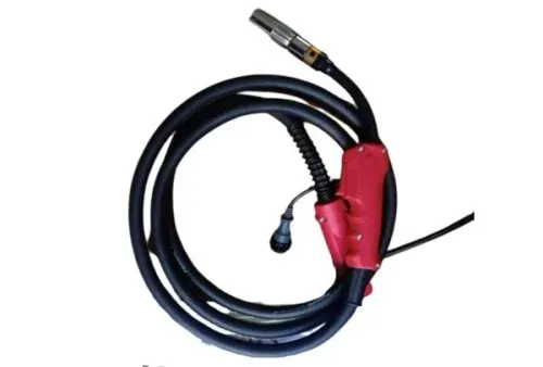
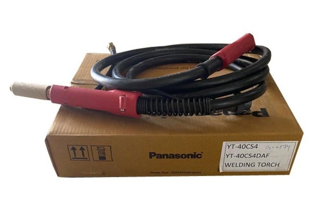
| Welding circuit | MIG torch, torch liner, contact tips, gas nozzle, torch trigger and spare tip | Standard equipment; spare tips may be optional |
| Work return | Earth-return cable with work clamp and machine-side connector | Standard equipment |
| Wire feeding | Wire-spool adaptor, spool brake, drive-roll set and roll groove marking | Standard equipment; extra rolls are optional |
| Shielding gas | Gas hose with fittings | Standard equipment |
| Gas control | CO2 regulator or regulator-flowmeter | Confirm separately; frequently optional |
| Consumables | Solid welding wire, contact tips, nozzles, liner and anti-spatter compound | Consumables; often purchased separately |
| Site equipment | CO2 cylinder, cylinder restraint or trolley, PPE, extraction and suitable outlet or plug | Not normally included |
Ask the seller to mark each line as included, optional, or excluded. A regulator for pure CO2 is not automatically suitable for an argon/CO2 blend, and a wire spool is not proof that the machine is ready for production.
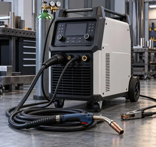
A CO2 welding machine also needs the correct torch, return connection, gas circuit and wire-feed parts; the power source alone cannot weld.
Which CO2 MIG machine specifications must be confirmed?
A 300 A label is incomplete: confirm the current at its rated duty cycle, test temperature and input supply. Request the complete co2 mig machine specifications, not the front-panel maximum.
| Specification | Figure to confirm | Why it matters |
|---|---|---|
| Input supply | Voltage, single or three phase, frequency and maximum input current | An unsuitable supply causes nuisance trips, overheating or poor output |
| Output | Welding-current range, rated output current, duty cycle percentage and output-voltage range | “300 A” has no meaning without the time rating and voltage conditions |
| No-load voltage | Open-circuit voltage in volts | It affects arc starting and must be checked during acceptance testing |
| Wire feed | Speed range in metres per minute and control method | The range must suit the wire diameter and welding current |
| Wire compatibility | Usable wire diameters, solid and flux-cored compatibility, and drive-roll profiles | Incorrect rolls or wire size cause slipping, bird-nesting and burnback |
| Spool capacity | Maximum spool diameter, width, weight and adaptor type | A spool that physically fits can still overload the hub or brake |
| Efficiency and power | Rated power consumption, efficiency percentage and power factor | These figures determine supply capacity and running cost |
| Enclosure | IP protection rating, insulation class and operating-temperature range | Dust, moisture and heat shorten component life |
| Size | Overall length, width, height and machine weight | Confirm it fits the work area and handling equipment |
For an inverter igbt co2 mig machine, also require a loaded test at the stated wire diameter and gas. Check stable feed, current response, thermal protection, gas-solenoid operation, trigger control and polarity; a power-up display proves none of these.
What gas, wire and polarity does the machine support?
An inverter IGBT CO2 MIG welding machine is a power-source design, not a separate welding process. A listing should state whether it runs solid wire with pure CO2, solid wire with an argon-rich blend, self-shielded flux-cored wire, or more than one of these options. The label “CO2 welding machine” alone does not answer that question.
| Process | Wire and shielding | Normal polarity |
|---|---|---|
| Solid-wire MIG/MAG | Mild-steel solid wire with pure CO2 or an argon/CO2 blend | DCEP: torch positive, work return negative |
| Self-shielded flux-cored | Flux-cored wire without a shielding-gas cylinder | Usually DCEN, but follow the wire manufacturer’s instruction |
| Gas-shielded flux-cored | Flux-cored wire plus the specified shielding gas | Polarity depends on the wire classification |
For gas operation, verify a cylinder connection that matches the gas supplier’s valve, a CO2-rated regulator/flowmeter, and a leak-free gas hose with the correct fittings. Pure CO2, argon/CO2 mix and argon require the correct regulator service; do not treat their connections or flow settings as interchangeable.
Excessive CO2 flow can freeze the regulator or create dry ice, while drafts, a misplaced nozzle or a leaking torch still cause porosity.
For flux-cored use, confirm that the machine has polarity-reversal terminals and that the torch, liner and drive-roll profile suit the selected wire. Ask for confirmation of:
- Solid-wire diameters and spool sizes
- Flux-cored wire compatibility
- Contact-tip and liner sizes
- The required gas and polarity for each wire type
How do you set up and commission CO2 MIG welding?
Start with a clean, dry test area and the manual’s CO2 MIG machine specifications. Confirm the torch connector, liner, contact tip, diffuser, nozzle and duty cycle match the wire and machine before energising it.
1. Fit the spool on the adaptor with the wire feeding from the bottom toward the drive rolls. Set the brake tight enough to stop overrun, not so tight that the motor slips.
2. Install drive rolls with the correct groove: V-grooves for solid steel wire, U-grooves for aluminium, and knurled rolls for flux-cored wire. Wrong grooves crush wire or cause bird-nesting.
3. Cut the wire cleanly, release the pressure arm, and feed it through the inlet guide, rolls, liner and contact tip. Set moderate roll pressure; excessive tension damages the liner and causes unstable feeding.
4. Connect the torch and work-return cable firmly. For solid steel wire with CO2 or argon/CO2 gas, select electrode-positive (DCEP); reverse polarity only when the wire manufacturer specifies it.
5. Attach the regulator or flowmeter and hose to the cylinder, check every joint with leak-detection fluid, and open the valve slowly. Set the specified flow at the torch, not only at the regulator.
6. Check the nozzle, diffuser and contact tip, then make a test weld. Drafts, leaks, a blocked nozzle or inadequate post-flow produce porosity even with correct settings.
7. Treat burnback, spatter, surging or bird-nesting as feed-system clues first: inspect the liner, tip size, roll groove, spool brake and torch bends before blaming the inverter. Adjust voltage and wire speed only after feeding is smooth.
What should you verify before accepting the machine for production?
Accept the inverter IGBT CO2 MIG machine only after a documented production trial, not a visual power-up. Match the packing sheet to the delivered unit and record the serial number before installation.
1. Check for the welding torch, liner, contact tips, nozzle, earth-return cable, work clamp, gas hose, regulator or flowmeter, spool adaptor, drive rolls and power cable. Mark each missing item as included, optional or separately purchased.
2. Compare the nameplate with your supply: input voltage, phase, frequency, fuse or breaker capacity and earthing. A 300 A rating does not prove the workshop supply can operate the machine.
3. Set wire diameter, material, gas, polarity, voltage and wire-feed speed from the model-specific manual. Do not copy settings from another CO2 welding machine.
4. Run a no-load test for display operation, open-circuit voltage, fan, wire-feed response and torch-trigger control. Then weld at the stated wire diameter and shielding gas, checking current response, arc stability, penetration, spatter and porosity.
5. Operate the gas trigger and confirm solenoid opening, actual flow at the torch, leak-free connections and adequate post-flow. Inspect the nozzle and diffuser first.
6. Confirm thermal protection trips and resets correctly without blocked airflow. Repeated trips justify specialist inspection of the fan, thermistor, rectifier and power modules; Weld Tech Corporation can assist with testing or repair before production acceptance.
Related product
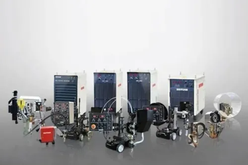
 | MIG Welding Machines Digital + Inverter IGBT-Controlled MIG/MAG Welding Machine Available in 250 AMP, 400 AMP & 500 AMP options Energy Saving & High Reliability Soft Arc (Thin Metal) & Hard Arc (Thick Metal) Characterisitcs... View product → |
Frequently asked questions
Which accessories should come with an inverter IGBT CO2 MIG machine?
Check the packing sheet for the welding torch, work clamp and cable, electrode or power cable, gas hose, regulator, wire spool adaptor, contact tips, nozzle, tip wrench and manuals. Record each quantity, cable length, connector type and supplied wire diameter.
Which CO2 MIG machine specifications must be confirmed?
Confirm rated input voltage and phase, input protection, output current and voltage range, duty cycle at its stated test temperature, wire-feed speed range, supported wire diameters, torch connection, spool capacity and machine weight.
What gas, wire and polarity does a CO2 MIG machine support?
Verify whether the machine and welding procedure use 100% carbon dioxide or an argon-CO2 mixture. Match solid or flux-cored wire diameter to the feeder and set polarity according to the wire manufacturer's data, commonly electrode positive for solid MIG wire.
How do you set up and commission CO2 MIG welding?
Secure the gas cylinder, fit the regulator and hose, install the correct wire spool, thread the wire, select polarity, set shielding-gas flow, and confirm feed direction. Run test welds while checking arc stability, gas coverage, wire feeding, bead profile and spatter.
What should you verify before accepting the machine for production?
Inspect the nameplate, accessories, cables, connectors, torch, regulator and warranty documents. Test the machine under load, confirm stable output and wire feeding, check gas leaks and safety functions, and record the test settings and results.