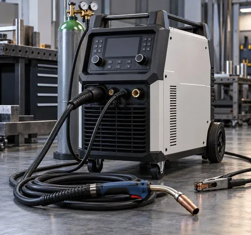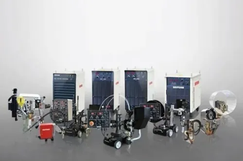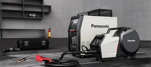

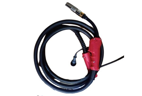
A production weld depends on more than the amperage shown on the front panel: the power circuit, wire path, gas coverage, work return and control settings must act as one system. By following the current path and weld sequence, you can set up a mig mag welding system, choose the right transfer mode and judge whether a 250 A, 400 A or 500 A machine fits the job.
Key takeaways
- A six-pulse SCR bridge controls rectified welding current by changing thyristor firing angle.
- Match wire diameter, shielding gas and transfer mode to joint thickness and position.
- Set wire speed, voltage, inductance and burnback while watching arc stability.
- Choose 250 A, 400 A or 500 A from duty cycle and production load.
From three-phase input to controlled welding current
Three-phase factory power first passes through a contactor and a mains-frequency transformer, which reduces the voltage and increases available welding current. A six-pulse SCR (thyristor) bridge then rectifies the transformer’s AC. By changing each thyristor’s firing angle, the control circuit regulates the average DC output.
A smoothing reactor limits rapid current rise and shapes short-circuit transfer. More inductance reduces harsh transfer and spatter; too much makes re-ignition sluggish. In constant-voltage operation, the control loop coordinates firing angle, output voltage and wire-feed speed. As wire speed rises, the electrode melts faster, so welding current rises to maintain the selected arc voltage.
The feeder pushes wire through the torch while the gas solenoid supplies shielding gas; the work lead and return clamp complete the circuit.
| Architecture | Fully thyristorised MIG/MAG | IGBT inverter MIG |
|---|---|---|
| Power stage | Transformer, SCR bridge, reactor | High-frequency switching transistors, transformer, rectifier |
| Control response | Tied to line frequency and transformer response | Rapid electronic switching and feedback |
| Practical result | Heavy, robust, serviceable, with strong overload tolerance | Smaller and lighter, with faster arc correction |
A fully thyristorised MIG/MAG source suits a durable MIG/MAG welding system, but it reacts more slowly than an IGBT inverter to rapid arc-length changes. A poor return connection or damaged torch cable can mimic a power-source fault.
How the feeder, torch and work return complete the circuit
At the trigger, the feeder motor pushes the electrode through the drive rolls and liner. The wire passes through the contact tip, which transfers current into it, and exits the nozzle toward the joint.
The gas solenoid opens at the same time, sending shielding gas through the torch passage so it surrounds the wire and arc instead of allowing atmospheric oxygen and nitrogen into the molten pool.
With electrode-positive operation, the three working paths are:
- Current: the positive machine terminal, torch cable, contact tip, wire, arc, workpiece, work clamp, return lead and negative terminal.
- Wire: feeder rolls, liner, contact tip and arc, where the electrode melts into droplets.
- Gas: regulator and hose, solenoid, torch passage and nozzle, where the gas spreads around the arc.
The work return is part of the welding circuit, not just a safety attachment. A loose clamp, corroded contact or damaged torch cable creates voltage drop; the arc then wanders, stubs or produces excess spatter, leading you to suspect the MIG welding machine when the fault is in the circuit.
The thyristor control loop responds to arc-voltage changes while the feeder maintains wire delivery. A worn tip or excessive tip-to-work distance alters current transfer and destabilises the weld.
Choosing wire, gas and transfer mode for the joint
Choose the transfer mode by matching wire diameter, wire type, gas and electrical settings to the joint, not by current alone. In a constant-voltage mig mag welding system, wire-feed speed largely sets current because faster wire requires faster melting; voltage sets arc length.
A thyristorised mig machine also coordinates firing angle, transformer output and reactor response, so the same panel settings can feel different on another machine.
| Mode | Wire and gas | Voltage, wire-feed speed and inductance | Travel result |
|---|---|---|---|
| Short-circuit | Small solid wire; argon/CO2 or CO2 | Lower voltage; moderate wire-feed speed; increased inductance softens short-circuit current and reduces spatter | Slow travel raises heat and burn-through risk; use for thin or positional joints |
| Globular | Larger wire or excessive wire-feed speed; CO2 promotes it | Voltage is too low for spray; moderate inductance leaves large, irregular drops | Slow travel produces a large, spattering puddle |
| Spray | Larger solid or metal-cored wire; argon-rich gas with sufficient argon | Higher voltage and wire-feed speed reach the spray threshold; too much inductance can blunt arc response | Travel fast enough to control heat and bead width |
Changing from argon/CO2 to pure CO2 demands retuning voltage, inductance and wire-feed speed. Increase wire diameter and the required current rises; reduce travel speed only when the joint needs greater deposition or fusion. A test bead must confirm transfer, penetration and spatter after any change.
Setting manual and synergic controls without losing arc stability
Set the job around the joint, not the machine’s maximum amperage. On a production MIG welding machine, record the wire diameter and type, shielding gas, transfer mode, wire-feed speed, arc voltage, inductance and travel speed.
- Select the wire and gas combination specified for the material and joint.
- Set wire-feed speed to establish deposition rate and welding current.
- Set voltage to control arc length and bead profile.
- Adjust inductance for short-circuit smoothness and spatter control.
- Fix travel speed and stickout in the work instruction.
A synergic program unifies these controls: you enter wire type, diameter, gas and a wire-feed speed, then the control assigns a matching voltage. As feed speed rises, the electrode melts faster and current rises; the control loop changes thyristor firing angle and output to hold the programmed arc relationship.
Use the trim control only to correct bead shape or arc length after a test bead.
Manual control is better when the wire, gas or joint has no reliable synergic curve, or when fit-up, position and stickout vary. It lets you change voltage and wire-feed speed independently.
That freedom matters on an older fully thyristorised MIG/MAG system, where inductance and transformer response can make a preset combination too harsh, too soft or unstable.
Running the weld from preflow to burnback
A production weld starts with a clean, continuous circuit. On a thyristorised MIG machine, a fault in the return lead or torch can look like unstable power, so check the complete MIG/MAG welding system before changing settings.
1. Inspect the wire path. Confirm the correct spool, tight feeder-roller pressure, straight liner, clean contact tip and unrestricted nozzle. Cut off a bird-nested or rusty wire end.
2. Prove shielding and return. Open the cylinder, confirm the regulator setting, trigger preflow and watch gas emerge evenly from the nozzle. Clear spatter from the gas holes. Clamp the work return to bright, clean metal and check both cable connections.
3. Make a test bead on matching scrap. Use the production wire, gas, voltage and wire-feed speed; check arc sound, penetration, bead shape and porosity before touching the joint.
4. Start the joint with preflow, establish the arc, then maintain the qualified travel speed and torch angle. Keep the nozzle distance consistent so air does not enter the shield.
5. At the stop point, release the trigger without pulling away. Let postflow cover the cooling pool, and set burnback only long enough to prevent wire freezing in the pool or tip; excessive burnback melts wire into the tip and causes failures.
Matching 250 A, 400 A or 500 A to the production load
Choose the rating from the current required during the weld, then verify that current against duty cycle and takt time. A nameplate maximum is not a continuous-welding promise: exceeding its stated duty cycle can trip thermal protection and overheat the transformer, rectifier or thyristors.
| Rating | Select it when | Reject it when |
|---|---|---|
| 250 A | Thin plate, smaller wire and short welds keep peak current within the duty-cycle limit | Long seams or high deposition demand frequent thermal trips |
| 400 A | Medium-to-heavy joints need more wire feed and arc-on time | The work rarely exceeds the 250 A range |
| 500 A | Large wire, deep sections, high joint volume and sustained production justify the capacity | The feeder, torch, cable or work return is not rated for the load |
Calculate arc-on fraction as welding time divided by takt time. Include tacks, stops and cooling; a short takt with repeated long welds can overload a fully thyristorised MIG MAG power source even when each individual weld looks acceptable. Plate thickness sets joint volume, while wire diameter sets the practical current and deposition range.
On a mig welding machine, select the thyristorised mig machine whose rated output covers peak current at that arc-on fraction, with clean airflow and sound cables. Weld Tech Corporation can test the return circuit, torch and feeder before you replace a power source that is merely undersized—or poorly connected.
Related product
 | MIG Welding Machines Fully Thyristorised MIG/MAG Welding System Available in 250 AMP, 400 AMP & 500 AMP options Six phase thyristorised system gives ripple-free DC output superior quality welding Synergic mode... View product → |
Frequently asked questions
How does a fully thyristorised MIG/MAG machine control welding current?
A mains-frequency transformer reduces three-phase voltage, then a six-pulse SCR bridge rectifies it. The control circuit regulates average DC output by changing thyristor firing angle.
How do the feeder, torch and work return complete the welding circuit?
The feeder pushes wire through the torch, while the power cable energises the contact tip. Current travels through the wire and arc into the workpiece, then returns through the work lead and clamp.
How do you choose wire, shielding gas and transfer mode?
Choose wire grade and diameter for the base metal and joint, select gas for the wire and transfer process, then use short-circuit, globular, spray or pulsed transfer according to thickness, position and heat input.
What controls must you set for a stable production MIG weld?
Set wire speed and voltage or trim, then adjust inductance, preflow, postflow and burnback. In synergic mode, select the wire and gas program before correcting arc length or trim.
When should you choose a 250 A, 400 A or 500 A MIG/MAG system?
Choose by required welding current, duty cycle, wire size, joint thickness and production time. A higher-rated machine suits longer welds and heavier sections only when the work requires its output.