
A Panasonic MIG feeder that birds-nests, burns back, surges, or stops feeding is not automatically suffering from a failed motor or control board. By tracing the wire path in a fixed order, you can separate spool, drive-roll, liner, contact-tip, torch, grounding, shielding-gas, and machine faults before replacing parts.
Key takeaways
- Trace wire movement from spool to contact tip before replacing feeder parts.
- Set spool tension and drive-roll pressure without crushing or slipping the wire.
- Replace contaminated liners and worn contact tips that create feeding resistance.
- Test a known-good wire spool before blaming the welding machine.
Start at the Spool and Trace the Complete Wire Path
Before replacing a feeder or control board, trace the wire from spool to contact tip. Most Panasonic MIG wire feeding problems become visible in this path during the stoppage.
1. Stop the machine and inspect the spool. Confirm the wire end is secured, the reel sits squarely on its adapter, the arrow or feed direction is correct, and the flange is not cracked or rubbing the holder.
A crossed coil, dragging reel, rust, grinding dust, or white oxidation can cause sudden stoppage, surging, or an unstable arc.
2. Read the spool label against the procedure. Record wire diameter, classification, lot or spool number, and installed contact-tip size. A diameter mismatch changes actual amperage, deposition rate, arc length, and feed resistance even when the programmed settings look correct.
3. Watch the wire at the drive rolls. Slipping, flattened wire, or a groove packed with debris points to roll selection, contamination, or pressure—not a failed motor. Bird-nesting at the inlet indicates resistance farther along the path or excessive pressure upstream.
4. Release the torch from sharp bends and feed with it straight. Resistance that remains points toward a worn or contaminated liner, restricted contact tip, or seized tip. Do not force the wire through.
5. Install a known-good spool of the same diameter and classification, with a new tip and clean or replacement liner. If feeding returns to normal, industrial welding consumable faults are more likely than a machine fault; if not, test the drive motor, encoder, feeder control, grounding, and parameters next.
Keep the record specific: spool, liner, tip, drive rolls, and symptom—not only the fault code.
Correct Spool Setup and Drive-Roll Pressure Before Adjusting Parameters
Set the spool brake so the flange stops without freewheeling, but never tighten it enough to make the feeder pull against heavy drag. Excess brake tension can make the drive rolls slip or surge; too little tension lets the spool overrun when the trigger stops, creating loops that tangle inside the spool.
1. Fit the spool fully onto the adapter, confirm the wire unwinds from the correct side, and check that the flange is not cracked or warped. A loose adapter or misaligned spool makes the wire rub the flange, then feeds unevenly.
2. Match the drive-roll groove to the wire. Use a V-groove roll for 0.8 mm solid steel wire such as ER70S-6; use a U-groove roll for aluminum. The wrong groove causes slipping, scoring, or crushed wire, all of which increase liner drag.
3. Reduce roll pressure until the wire slips, then increase it only enough to feed steadily. Excess pressure flattens steel, scores aluminum, creates metal dust, and can drive a damaged section into a bird-nest at the inlet guide.
4. Stop immediately if wire bunches behind the rolls. Continuing to pull the trigger packs the nest into the feeder and can turn a simple spool or pressure fault into a teardown.
Record the wire diameter, classification, spool lot, roll type, and pressure setting with other welding consumables. This makes Panasonic MIG wire feeding problems easier to separate from motor or control faults.
Inspect the Liner, Contact Tip, and Torch for Mechanical Resistance
Mechanical resistance is the likely cause when the drive motor strains, the wire stops with the torch bent, or feeding improves after removing the contact tip. Do not blame wire diameter or electrical connection until you test the path with the torch held straight and the contact tip removed.
- A blocked liner resists hand-feeding even with the tip removed. Rust dust, filings, or a sharp torch bend can create intermittent drag; clean or replace the liner and check that the guide aligns with the drive rolls.
- A seized contact tip allows smooth feeding without the tip but stalls when the tip is installed. The bore may be undersized, distorted, or fused with burnback. Fit a tip marked for the measured wire diameter.
- A torch-routing fault appears when a tight bend or crushed conduit changes feeding resistance. Straighten the torch, release the trigger, and clear any bird-nest before pulling more wire.
- An incorrect diameter leaves a consistent mismatch between the wire, drive-roll groove, liner, and tip. Measure the wire and compare its classification and diameter with the procedure and feeder settings.
- A poor electrical connection does not usually create mechanical drag. If wire movement stays smooth but the arc remains erratic, inspect the work clamp, cable lugs, torch connection, and ground path.
For Panasonic MIG wire feeding problems, install a known-good spool of the same classification and diameter, fit a new tip, and clean or replace the liner. If feeding stabilises, industrial welding consumable faults are more likely than a feeder board or drive motor.
Protect Wire Surface Condition During Storage and Shutdowns
Keep an unopened spool in its original sealed packaging until the day you load it. Store welding consumables in a clean, dry cabinet away from roof leaks, wash areas, grinding dust, and temperature swings that create condensation on cold metal.
After opening, protect the wire from atmospheric moisture and shop contamination. Fit the manufacturer’s cover or a clean plastic wrap, keep the spool off the floor, and do not touch the wire with oily gloves. Exposed surface contamination travels through the liner, fouls the contact tip, destabilises transfer, and can create porosity.
Before loading a spool, quarantine it if you find:
- Red rust, white oxidation, or dark staining on the wire
- Grinding dust, embedded particles, or lubricant residue
- Torn packaging or a crushed, cracked, or distorted flange
- A loose inner core that lets the spool wobble
- Wire crossed, tangled, or pulled beneath another layer
For a partial spool, cut the wire cleanly and secure its end in the flange hole or retaining clip; never leave a loose end on the coil. Cover the spool during shutdowns, and remove it from the feeder for extended stoppages when moisture or contamination cannot be controlled.
Record diameter, classification, spool or lot number, and storage condition in your MIG welding wire maintenance log. A clean surface cannot compensate for the wrong wire diameter or damaged drive components.
Use a Controlled Substitution Test Before Blaming the Welding Machine
A known-good spool is the quickest separator between industrial welding consumable faults and a machine fault. Use the same wire diameter and classification, install a new contact tip, clean or replace the liner, and hold the torch straight during the test.
1. Record the original spool, liner, tip, drive-roll condition, wire-feed speed, voltage, and fault symptom. This record prevents a parameter mismatch from masquerading as a Panasonic wire problem.
2. Fit the known-good spool and check that the reel brake stops coasting without creating drag. Confirm the correct drive-roll groove, moderate roll pressure, and smooth feeding to the tip. If bird-nesting, burnback, surging, or stubbing disappears, suspect the original wire, spool, or consumable path.
3. If the symptom remains, inspect the feeder motor, encoder, control response, and actual feed speed. A drive fault becomes more credible when the wire path feeds freely but speed surges or stops.
4. Clean the workpiece and clamp, tighten the ground connection, verify shielding-gas flow and hose integrity, and check the nozzle for spatter blockage. Then restore the approved voltage, wire-feed speed, inductance, and gas setting; incorrect values can imitate feed trouble through porosity or unstable transfer.
MIG welding wire maintenance records should identify the spool or lot, liner, tip size, and roll condition. Use a specialist repair service, such as Weld Tech Corporation, after these checks point to the feeder control, encoder, or power source rather than replacing boards on suspicion.
Related products
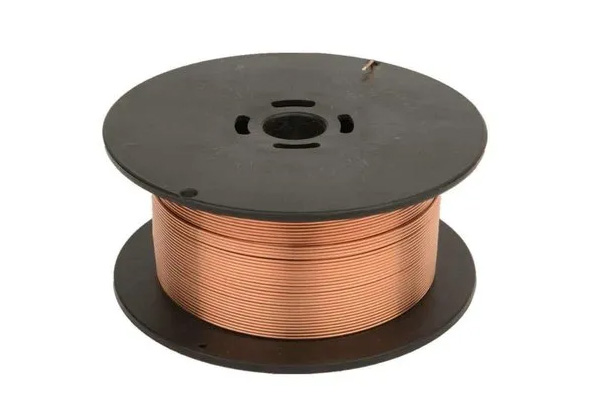 | MIG Welding Wires Brand Panasonic Usage / Application MS Welding Thickness 0.8 mm Wire Material Copper / Copper Alloy Grade ER70S-6 Yield Strength Greater-than or... View product → |
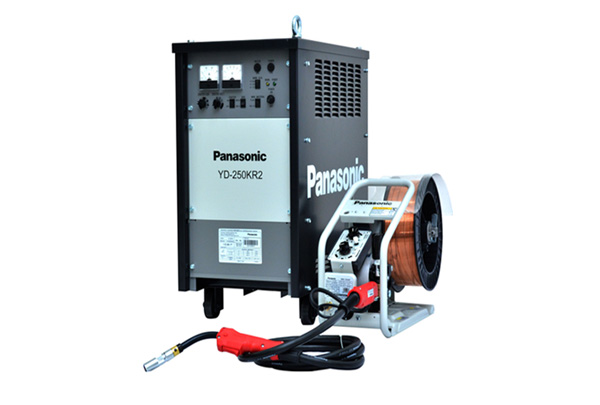 | MIG Welding Machines Panasonic MIG Welding Machines Brand Panasonic MODEL YD-250KR 2 INPUT SUPPLY 415 +10% ,-10% PHASE/FREQUENCY THREE / 50-60 HZ POWER CONSUMPTION 9.5 KVA/7.9KW WELDING CURRENT RANGE... View product → |
Frequently asked questions
Where should you start diagnosing Panasonic MIG wire feeding problems?
Start at the spool and trace the complete wire path through the drive rolls, liner, contact tip, and torch during the stoppage.
How do you set up a MIG wire spool and drive rolls correctly?
Seat the spool securely, set brake tension so it stops without overrun, match drive rolls to the wire, and increase pressure only until feeding is consistent.
Which torch parts cause mechanical resistance during MIG welding?
A blocked or worn liner, an incorrect or worn contact tip, sharp torch bends, and contamination inside the torch can restrict wire movement.
How can you determine whether the wire or welding machine is at fault?
Run a controlled substitution test with a correctly stored, known-good spool and the same settings; compare feeding before replacing machine components.
Related products
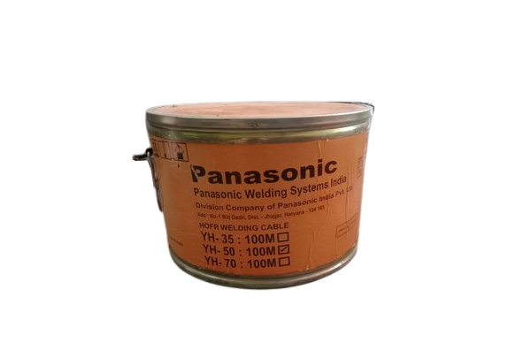 | Welding Cables Brand Panasonic Usage / Application Industrial Wire Material Copper / Copper Alloy Size 35 sq mm, 50 sq mm, 70 sq mm, 95 sq mm Country of Origin Made... View product → |
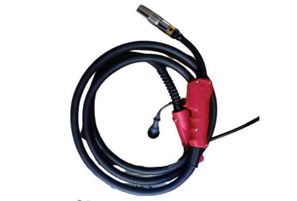 | MIG Welding Torch We are Manufacturer, Distributor, Supplier of MIG Welding Torches, MIG Welding Torch View product → |
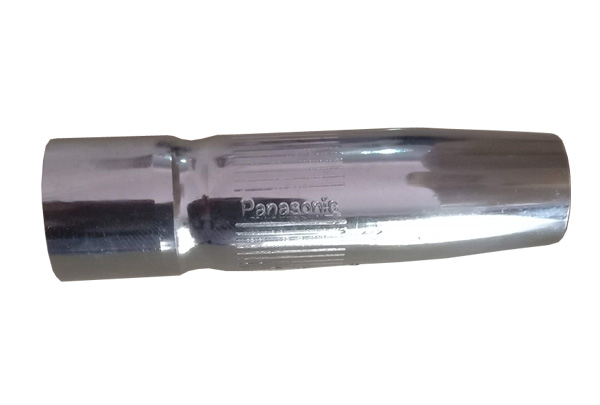 | Welding Spare Parts We are Manufacturer, Distributor, Supplier of Welding Spare Parts View product → |