
A TIG fault can originate in the power source, work-return circuit, shielding gas, torch, controls, or material preparation. By following a symptom-led sequence, you can separate setup errors from equipment failures, correct common automotive weld defects, and identify when a qualified tig welding repair is safer than continued testing.
Key takeaways
- Record power, gas, control response, and arc behavior before changing settings.
- Check input power, work return, and shielding gas before replacing parts.
- Inspect the torch, tungsten, material preparation, and process settings together.
- Choose TIG when controlled heat and a clean finish justify slower work.
Classify the symptom before changing a setting
A machine that powers up can still have a failed gas circuit, torch switch, remote control, work return, or high-frequency start. Record four observations before changing a setting: does it power up, deliver gas, respond to the torch switch or pedal, and create an arc?
1. Treat the machine as four circuits: input power, welding-current output, shielding gas, and torch/control accessories. A no-arc fault points to input power, open-circuit start, torch-switch wiring, remote-control mode, work return, or failed high-frequency ignition.
2. A weak or unstable arc points to poor grounding, incorrect polarity, tungsten contamination, gas loss, or an output fault. Arc wandering points to damaged or incorrectly ground tungsten, excessive stick-out, a blocked nozzle, or magnetic effects.
3. For spatter, porosity, crater cracking, undercut, lack of fusion, or inconsistent bead appearance, record amperage, travel speed, filler timing, gas settings, joint cleanliness, and material thickness. That record shows whether the weld changed because of the machine or the technique.
4. Check one circuit and one variable at a time. This symptom log forms the basis of effective tig welder troubleshooting and prevents random adjustments from hiding the original fault. If the fault follows a torch, control, cable, or gas component, the power source is not the first part to replace.
Check input power, work return, and shielding gas in order
Check input power, work return, and shielding gas in that order; this sequence isolates many TIG welding machine problems before you change welding settings.
1. Read the nameplate for input voltage, phase count, frequency, and permitted voltage range. A three-phase 415 V machine is not interchangeable with every 415 V connection.
2. Check phase presence, fuses, breakers, terminal tightness, supply cables, ventilation openings, and alarm history. A powered display does not prove that all phases or output circuits work.
3. Inspect the work clamp jaws, cable lugs, quick-connects, and bare contact area on the vehicle. Remove paint, rust, seam sealer, anodizing, and contaminated fixture material; a poor return causes unstable starts and local heating.
4. Trace the gas path from cylinder valve and argon identification through the regulator, flowmeter, solenoid, hose, torch fittings, collet body, and cup. A blocked solenoid or cracked fitting can mimic an arc fault.
5. Begin at 10–15 L/min, or 20–32 ft³/h, then adjust for cup size, gas lens, joint access, and drafts. Excessive flow creates turbulence and draws air into the shield, so raising flow is not a reliable porosity cure.
6. Brush leak-detection solution over the cylinder connection, regulator, hose joints, solenoid fittings, torch head, and cup. Pressurise the system, close the cylinder valve, and watch for bubbles or pressure loss.
Confirm actual flow at the torch with its valve open. A flowmeter reading alone does not prove delivery during welding, a leak-free closed valve, or an intact gas path.
Correct the torch, tungsten, material preparation, and process settings
1. Match tungsten diameter and type to the joint amperage and polarity; use the manufacturer’s range rather than guessing. Grind longitudinally, never around the electrode. After tungsten touches the workpiece or filler, remove and replace the contaminated section. A suddenly balling electrode also warrants a polarity check: DCEP overheats tungsten and reduces penetration.
2. Inspect electrode protrusion, collet grip, gas-lens holes, ceramic cup size, blocked nozzle, cracked torch body, worn cables, and torch current rating. Use DCEN for ordinary steel and stainless repairs. Use AC for aluminium: electrode-positive time disrupts oxide, while electrode-negative time supplies penetration.
3. Prepare aluminium in two stages. Solvent removes oil, but a dedicated stainless brush used only on aluminium removes oxide; remove adhesive, marker, degreaser, and solvent residue before diagnosing the power source. AC balance and frequency cannot replace cleaning: more electrode-positive time cleans harder but heats tungsten, while more electrode-negative time penetrates deeper.
4. Set amperage, AC balance, AC frequency, pulse frequency, pulse width, pre-flow, post-flow, upslope, downslope, crater current, and local or remote-current control for the joint, then change one variable at a time. Check bay-door drafts, vehicle fans, and compressed-air blow-off before raising gas flow.
This disciplined sequence makes a tig welding machine for troubleshooting useful rather than a source of random adjustments.
Separate a machine fault from a torch or control fault safely
Substitute a known-good torch, cable, regulator, tungsten, work clamp, and gas supply one at a time; changing several together hides the failed part. After each change, test the same joint and record:
- Open-circuit voltage and current response as the pedal or hand control moves
- Torch-switch continuity, connector condition, and selected local or remote mode
- Alarm code, welding mode, polarity, gas setting, and whether the fault occurs at idle or only under load
| Observation | More likely external fault | More likely machine fault |
|---|---|---|
| Open-circuit voltage present, no current command | Pedal, hand control, switch wiring, connector, or remote-mode error | Control input circuit after external checks |
| Arc fails only under load | Gas delivery, work return, torch rating, overheating, or duty-cycle limit | Output stage after external checks |
| Fault appears at idle | Connector, control circuit, alarm, or interlock | Power-source control or protection circuit |
For a water-cooled torch, check coolant level, kinked hoses, blocked passages, pump noise, and flow-switch behaviour. Never bypass the cooler interlock. A hot shop, blocked air passages, or welding above the specified duty cycle can trigger thermal shutdown; let the unit cool and inspect ventilation before calling it an intermittent inverter failure.
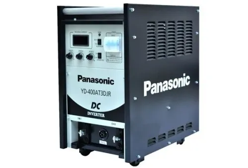
Keep HF cables away from vehicle wiring, scan tools, chargers, and communication equipment. Use lift-arc when the procedure permits. Panasonic TIG welding issues require the exact model, option board, torch, connector, and service manual because alarm codes and parameter names differ.
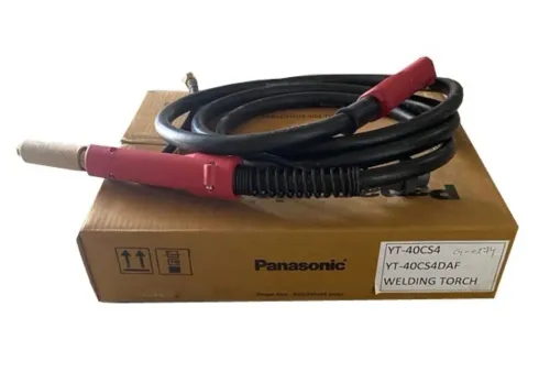
Weld Tech Corporation can help match Panasonic torches, consumables, spare parts, and gas-control components. Disconnect input power before service; capacitor, control-board, and output-stage testing belongs to a qualified technician following the manufacturer’s procedure.
Related products
 | TIG Welding machine Panasonic TIG Welding Machines Model Number 300 TSP Welding Type TIG Welding Voltage 415V, +10% (Input Voltage) Output Current Range 5-300 A Brand Panasonic Frequency 50-60 Hz... View product → |
 | ac/dc tig welding machine Full Digital AC/DC TIG Welding Machine A variety of waveforms ensures superior welding for aluminum and a wide range of metals. View product → |
Choose TIG only when the automotive repair justifies its control
TIG earns its place for clean mild-steel and stainless brackets, thin exhaust sections, and visible repairs where heat control and finish matter. Use DCEN for these jobs.
Use AC for aluminium panels, castings, and components after removing oil with solvent and oxide with a dedicated stainless brush; cast aluminium needs extra pre-cleaning because embedded contamination can cause porosity.
Thin body panels punish a long molten pool with burn-through, distortion, and crater cracking. Use low heat, short welds, downslope, and crater current. Before blaming the machine for undercut or lack of fusion, check amperage, arc length, travel speed, joint fit-up, and filler technique.
| TIG | Controlled heat and clean finish | Brackets, exhaust sections, aluminium, visible repairs |
|---|---|---|
| MIG | Faster deposition | Longer mild-steel seams |
| Spot welding | Consistent overlapping joints | Many body-panel assemblies |
| Brazing | Lower-temperature joining | Selected thin or coated repairs |
| Replacement | Removes preparation and access risks | Stressed, corroded, or inaccessible parts |
If the fault remains after checking supply, gas flow and leaks, polarity, torch consumables, work return, remote controls, cooling, ventilation, and alarm history, stop using the equipment.
Preserve the recorded settings and alarm history, then arrange tig welding repair; never open an inverter power source containing charged capacitors without the manufacturer’s procedure and qualified electrical service.
Frequently asked questions
What should you check first when a TIG welding machine has problems?
Record whether the machine powers up, delivers gas, responds to the torch switch or pedal, and creates an arc. Then check input power, work return, and shielding gas in that order.
How do you distinguish a TIG machine fault from a torch or control fault?
Separate the torch, torch switch, pedal, and control connections from the machine’s basic functions. Test each safely so you do not replace the power source for a failed accessory.
What should you inspect when TIG welding produces poor automotive results?
Check torch condition, tungsten preparation, material cleanliness and fit-up, shielding gas delivery, and process settings before changing machine components.
When is TIG the right choice for automotive repair?
Choose TIG when precise heat control, a clean weld, and careful work on suitable automotive material outweigh the slower process and higher operator-control demands.
Related products
 | TIG Inverter Welding Machines Panasonic TIG Inverter Welding Machines Brand Panasonic MODEL YC-400TX3 INPUT SUPPLY 415 + - 10% PHASE/FREQUENCY THREE / 50-60 HZ RATED INPUT CAPACITY 13.9 KVA/13.2 KW RATED OUTPUT CURRENT... View product → |
 | TIG Welding machine IGBT Controlled DC Pulse TIG Welding Power Source Suitable for TIG/MMA Welding Stable current output even at 5 AMP Sheet thickness even 0.5mm weldable Pulse Frequency upto 500 Hz Digital Display of... View product → |