
A thyristorised power source can look mysterious because its current control happens inside a transformer–rectifier circuit rather than an inverter. By following the power path, arc controls and workload calculations, you can identify how the system operates, set it correctly and judge whether a machine suits your production needs.
Key takeaways
- Earlier SCR firing raises average welding voltage and current.
- Match 250 A, 400 A or 500 A to duty cycle and material thickness.
- Check wire size, gas, torch rating, input supply and control compatibility.
- Confirm machine availability, service history, spares and repair support before committing.
How phase-controlled rectification creates welding DC
A three-phase transformer supplies reduced-voltage AC to a six-thyristor bridge. Each silicon-controlled rectifier (SCR) conducts only after its gate receives a firing pulse, so the control circuit chooses the firing angle: earlier firing gives a higher average DC output, while later firing gives a lower one.
The bridge produces six-pulse DC, with ripple at about 300 Hz on 50 Hz mains or 360 Hz on 60 Hz mains.
A smoothing inductance reduces that ripple and stores energy between pulses. It also shapes short-circuit behaviour: more inductance slows current rise, softening the arc and reducing harsh spatter; excessive inductance can make re-ignition sluggish. This adjustment is separate from voltage.
In a fully thyristorised MIG MAG system, the main welding-power path is controlled by thyristors rather than fixed diodes or an inverter switching at high frequency. The transformer remains a conventional low-frequency transformer, so electronic control does not make the machine an inverter.
- In constant-voltage operation, wire-feed speed chiefly sets welding current and deposition rate.
- The voltage setting mainly changes arc length; raising voltage without correcting wire-feed speed can create a long, unstable arc.
- The control circuit synchronises firing pulses, output switching and remote settings so the DC supply responds to wire contact and arc interruption.
That regulated DC travels through the contact tip, wire and arc to the work return. The feeder’s motor, gas valve and control cable must match the power source; a different feeder is not automatically compatible.
What happens from the input terminals to the arc
The power path begins at the three-phase input terminals and ends where current crosses the arc gap. In a MIG welding machine, each stage passes energy forward while the control circuit coordinates output voltage, wire speed, gas and contactor operation.
- The input circuit feeds three-phase AC to the transformer. The transformer provides isolation and reduces the mains voltage to a high-current welding voltage; its turns ratio sets the usable output range.
- The transformer secondary supplies the six-thyristor bridge. The control circuit fires each thyristor at a selected point in its AC half-cycle, so the bridge changes the low-voltage three-phase waveform into adjustable welding DC.
- The rectified output enters the smoothing circuit. A smoothing inductance reduces the six-pulse ripple—about 300 Hz on a 50 Hz supply—and limits how quickly current rises during a short circuit.
- The feeder motor pulls wire from the spool through the liner and pushes it into the torch. Its speed controls how much electrode enters the arc, while the contactor or output switch connects welding power only when the trigger is pressed.
- Inside the torch, the contact tip transfers current into the continuously fed wire. Shielding gas from the solenoid and regulator exits the nozzle, displacing air around the molten weld pool.
- Current travels from the tip through the wire and arc into the workpiece, then returns through the work clamp, return lead and machine terminal. The control cable links trigger, feeder, burnback and crater-fill functions, so incompatible pinouts or control voltages can stop an otherwise sound power source from operating correctly.
How wire, gas and controls determine transfer
Wire-feed speed sets current and deposition rate in a constant-voltage mig welding machine; voltage mainly sets arc length. Raise voltage without increasing wire speed and the arc becomes long, unstable and spattery. A worn liner, slipping drive roll or loose contact tip can also reduce actual current despite a normal voltage display.
Match transfer mode to the consumable and gas:
| Transfer mode | Wire, polarity and gas | Voltage, wire speed and inductance |
|---|---|---|
| Short-circuit | Small solid wire, usually DCEP, with CO2 or an argon-rich Ar/CO2 mix | Lower voltage and wire speed; add inductance to slow current rise and soften the arc |
| Globular | Solid wire, usually DCEP, with CO2 or an Ar/CO2 mix | Increase wire speed above short-circuit settings, but stay below spray conditions; moderate inductance limits spatter |
| Spray | Larger solid wire, DCEP, with argon-rich gas, commonly at least 80% argon | Higher voltage and wire speed; use enough voltage to maintain a stable axial arc and avoid excessive inductance |
Short-circuit transfer suits thin material, root gaps and out-of-position welding, but excessive voltage creates burn-through or spatter. Globular transfer deposits larger droplets and suits neither fine control nor overhead work. Spray transfer gives high deposition and a smooth arc, but its fluid pool demands suitable thickness and a flat or horizontal position.
For flux-cored wire, follow the wire maker’s polarity and gas specification; self-shielded wire often uses different polarity from gas-shielded wire. Set gas flow high enough to prevent porosity without creating turbulence.
A fully thyristorised mig mag system still needs a matched feeder, control cable, torch and contact tip: voltage, inductance and burnback controls are not interchangeable.
How to match 250 A, 400 A or 500 A to real work
A 250 A source suits light-to-medium fabrication; 400 A covers heavier plate and longer welds; 500 A is justified by sustained high deposition, not by plate thickness alone. Compare each rating at its stated duty cycle, normally a percentage of a 10-minute period at a specified ambient temperature.
1. Identify the heaviest weld: plate thickness, fillet size and joint position. Thin sheet and vertical or overhead joints need lower current; thick plate in the flat position permits higher current and larger wire.
2. Match wire diameter to the current range. As a working guide, 0.8 mm wire suits roughly 60–180 A, 1.0 mm 100–250 A, 1.2 mm 150–350 A, and 1.6 mm 250–500 A. Confirm the procedure before welding.
3. Check daily arc-on time. A 250 A machine rated at 60% delivers 250 A for six minutes in each ten-minute cycle; repeated near-continuous welding calls for a 400 A or 500 A unit with adequate duty cycle.
4. Set gas flow for the torch and nozzle, commonly 12–20 L/min for argon-rich MIG/MAG shielding. Excess flow creates turbulence; too little gas leaves porosity, especially in drafts.
5. Include wire-feed speed, because it determines current and deposition in a CV system. A fully thyristorised mig mag system rated 500 A still performs poorly if its feeder cannot sustain the required wire speed.
Choose the smallest rating that meets peak current and duty-cycle demand with thermal margin.
How to verify availability, compatibility and serviceability
A machine that shows the correct idle voltage can still collapse when an arc starts. Verify it under welding load, not only with a multimeter across the output terminals.
1. Confirm the site supply: three-phase voltage, frequency, phase sequence, protective-device rating and earthing arrangement. Compare these with the nameplate.
2. Match the feeder and source. Check control-cable pinout, motor voltage, wire-feed feedback, contactor logic, burnback, crater-fill, polarity and remote voltage or inductance controls. A compatible connector alone proves nothing.
3. Inspect the torch, contact tip, liner, work-return clamp, gas solenoid and output terminals. Damaged connectors create voltage drop and erratic wire feeding.
4. Ask about thyristorised MIG/MAG machine availability, replacement SCRs, control boards, transformer parts, feeder motors and documented wiring diagrams. An electrically repairable machine becomes uneconomical when its obsolete feeder card has no support.
5. Require a load test with the intended wire diameter, shielding gas and polarity. Use a welding load or calibrated resistive load, then record output voltage, current, ripple, wire-feed response and stability across low, mid-range and high control settings.
An SCR can pass a static test yet fail to fire reliably, commutate correctly or share current with the other bridge devices. Excessive ripple, unstable current, or welding at only certain settings points to firing-angle, control-board or bridge faults.
Ask a MIG/MAG welding system supplier such as Weld Tech Corporation to document these results before you accept the machine.
Related product
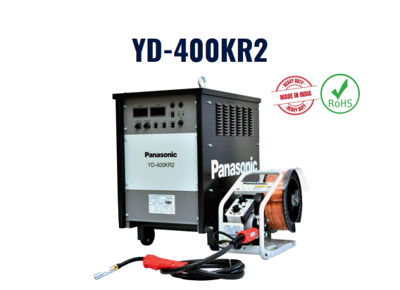 | MIG Welding Machines Fully Thyristorised MIG/MAG Welding System Available in 250 AMP, 400 AMP & 500 AMP options Six phase thyristorised system gives ripple-free DC output superior quality welding Synergic mode... View product → |
Frequently asked questions
How does phase-controlled rectification create welding DC?
A three-phase transformer feeds a six-thyristor bridge. Gate pulses set the firing angle, which controls the average DC output: earlier firing produces more output and later firing produces less.
What happens between the input terminals and the welding arc?
Three-phase AC enters the transformer, is reduced to welding voltage, passes through the SCR bridge and smoothing components, then reaches the torch, wire electrode and work return to establish the arc.
How do wire, shielding gas and controls affect metal transfer?
Wire diameter, wire-feed speed, voltage, inductance and shielding-gas mixture influence arc length, penetration, spatter and transfer mode. Set them as a matched group rather than adjusting one control in isolation.
How do you choose between a 250 A, 400 A and 500 A MIG MAG machine?
Compare required current, duty cycle, material thickness, wire size, torch rating and available input power. Choose the smallest machine that meets the required output at its stated duty cycle.