
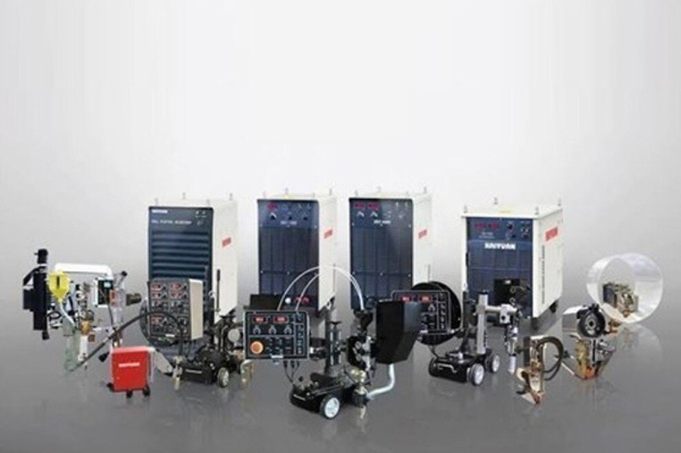
A SAW machine is built for a narrow but valuable job in vehicle manufacturing: depositing a large, consistent weld along an accessible seam in thick steel. By the end, you will be able to identify suitable automotive components, map the production workflow, compare SAW with competing processes, and specify the equipment and controls a production cell needs.
Key takeaways
- Use SAW for thick assemblies with long, accessible seams.
- Keep SAW away from thin body panels and short, awkward joints.
- Match wire diameter, flux, current, voltage and travel speed.
- Specify seam access, automation, inspection and production rate together.
What a SAW Machine Does and Which Automotive Parts Suit It
A SAW machine suits thick automotive assemblies with long, accessible seams—not thin vehicle bodywork. Submerged arc welding uses a continuous bare wire beneath a blanket of granular flux; the flux hides the arc, protects the molten pool and helps produce deep, consistent welds with high deposition rates.
Unfused flux can be recovered and returned to the hopper.
Common panasonic saw machine uses in automotive production include:
- Truck and trailer chassis rails with long longitudinal welds
- Frame cross-members and large structural brackets
- Axle housings and suspension components
- Wheel or rim assemblies requiring continuous circular seams
- Pressure vessels and other heavy fabricated assemblies used in vehicle manufacturing
These parts benefit from mechanised travel, stable fit-up and welding in the flat or horizontal position. A carriage, positioner and flux hopper can maintain repeatable travel over a seam that would be slow and inconsistent to weld manually.
| Component | SAW suitability | Main reason |
|---|---|---|
| Chassis rails | High | Thick steel and uninterrupted seams support deep, productive welds |
| Axle housings | High | Rotating fixtures provide access to continuous joints |
| Wheel rims | Conditional | Suitable when joint geometry permits controlled circular travel |
| Thin body panels | Poor | High heat input enlarges the heat-affected zone and causes burn-through, distortion or warping |
SAW also needs room for the welding head and flux delivery. Passenger-car body shells use resistance spot welding, laser welding and MIG or MAG more often because their thin, curved panels demand low heat input, rapid access and closely controlled weld appearance.
How a Production SAW Cell Makes and Checks the Weld
A production cell starts with joint preparation, not arc ignition. Operators clean mill scale, oil and moisture from the edges, set the specified root gap, align plate thicknesses, and tack-weld the assembly.
Excessive gap, mismatch or inconsistent edge preparation can cause burn-through, lack of fusion, slag inclusions or an uneven profile; a travel carriage cannot correct poor fit-up.
The welding head follows a programmed path while a hopper lays granular flux ahead of the arc. The flux covers the arc and weld pool, shielding them from atmospheric contamination and forming slag as the weld cools.
A feeder delivers the wire electrode at a controlled rate, while travel speed, current, voltage and polarity maintain penetration and bead shape. Single-wire, twin-wire and tandem-arc setups suit different deposition targets, but multiple wires demand tighter control of heat input, electrical coordination and flux coverage.
The operating sequence usually includes:
- Positioning the component flat or horizontal, with enough access for the welding head and hopper.
- Feeding the selected wire and flux combination for the steel grade, thickness and required toughness.
- Controlling travel speed and wire feed throughout the uninterrupted seam.
- Recovering clean, unfused flux through a vacuum or recovery unit, then screening and returning it to the hopper when permitted by the procedure.
- Removing slag mechanically after cooling; discard contaminated or damp flux.
- Checking the weld visually for undercut, overlap, crater defects and profile, then applying dimensional checks and specified non-destructive testing.
These controls make SAW practical for long, repeatable seams in industrial saw welding applications, but inspection still determines whether the weld meets the component procedure.
Where SAW Fits Compared with MIG, TIG, Spot, Laser and Robotic Welding
SAW belongs on thick, accessible automotive structures with long, uninterrupted seams—not on a vehicle body shell. For SAW welding for automotive manufacturing, its value is high deposition, deep penetration and repeatable mechanised travel, while its penalty is higher heat input, a wider heat-affected zone and greater distortion risk.
| Process | Speed and penetration | Heat input and access | Appearance and thin-sheet suitability |
|---|---|---|---|
| SAW | Very high deposition; deep, consistent penetration | High heat input; needs flat or horizontal access and flux coverage | Smooth, uniform bead under removed slag; poor for thin sheet |
| MIG/MAG | Fast and versatile; moderate penetration | Lower heat input than SAW; reaches varied joints with a torch | Visible bead; suitable for many medium and thin sections |
| TIG | Slow deposition; precise, shallow-to-moderate penetration | Low, controllable heat input; useful where torch access is good | Cleanest appearance; suited to thin sheet but inefficient for long production seams |
| Resistance spot | Extremely fast per weld; penetration is local through overlapping sheets | Low overall heat input; requires electrode access to both sides | Minimal visible marking; ideal for thin body panels, not long seams |
| Laser | Very fast on prepared joints; narrow, deep penetration | Low total heat input and small distortion; demands accurate fit-up and line-of-sight access | Narrow, clean weld; strong choice for thin sheet |
| Robotic welding | Repeatable speed depends on the process installed, usually MIG/MAG or laser | Access follows torch, gun or optics reach; programming adds setup time | Consistent process-specific finish; not a separate weld physics |
Choose SAW for chassis rails, axle housings or heavy subassemblies. Choose spot, laser or MIG/MAG for thin, overlapping body parts; a robot improves repeatability but does not make SAW suitable for a cramped joint.
How to Match the SAW Power Source, Consumables and Welding Settings
Weld quality, deposition rate and defect risk depend on the complete welding system, not the Panasonic power source alone. Match the wire chemistry and diameter to the base-steel grade, thickness, required toughness and flux classification under AWS A5.17, AWS A5.23 or ISO 14171.
Set polarity, current mode, voltage, wire-feed speed and travel speed as one procedure.
| Arrangement | Production effect | Control requirement |
|---|---|---|
| Single-wire | Stable, flexible deposition for one seam | One arc, one wire-feed circuit and consistent flux coverage |
| Twin-wire | Higher deposition with faster filling | Coordinated feeders, electrical isolation and sufficient flux depth |
| Tandem-arc | High productivity on long, accessible joints | Independent arc control, accurate spacing and controlled inter-arc interaction |
| Multi-wire | Maximum deposition on suitable heavy sections | Complex power coordination, rigid fit-up and strict heat-input control |
Heat input rises with current and voltage and falls as travel speed increases; estimate it from voltage × current × 60 ÷ travel speed, then apply the process efficiency used by your welding procedure. Excessive heat enlarges the heat-affected zone, slows cooling and increases distortion, while insufficient heat produces lack of fusion.
Control these variables before increasing deposition rate:
- Root gap, edge preparation, plate alignment and tack quality
- Flux type, dryness, delivery depth, recovery and contamination control
- Wire-feed speed, arc length, polarity, travel speed and interpass temperature
- Seam tracking, positioner speed and torch-to-joint alignment
A large wire or extra arc cannot correct a changing gap. Poor fit-up can cause burn-through, slag inclusions, an irregular profile or incomplete fusion even when the programmed settings are correct.
How to Specify a Panasonic SAW System for an Automotive Plant
Give the supplier a production drawing and cycle target, not only the phrase “SAW machine.” That information determines whether a Panasonic system can weld the part repeatedly within its takt time.
- Name the component, steel grade, thickness range, seam length, joint design and required welding position. State whether the seam is flat, horizontal or requires rotation.
- Provide the target deposition rate, travel speed, weld size, duty cycle and daily production volume. These figures determine whether single-wire, twin-wire or tandem-arc equipment is justified.
- Describe the available electrical supply, including phase, voltage, frequency, incoming capacity and earthing. Confirm that the plant can support the selected power source at its planned current.
- Specify the positioner’s required load capacity, rotation speed, workpiece dimensions, chucking method and allowable runout. An undersized positioner creates fit-up errors even when the welding source is correctly rated.
- State how unused flux will be collected, screened, dried, stored and returned to the hopper. Include the flux classification, wire chemistry and diameter required by the welding procedure.
- Identify the inspection standard, acceptance criteria and records required, such as visual inspection, magnetic-particle testing, ultrasonic testing or ISO 5817 quality level.
Ask Weld Tech Corporation to confirm spare-parts availability, commissioning responsibility, operator training and response time for service in Mumbai. The support plan should also cover seam tracking, flux recovery, calibration and procedure trials before production release. That evidence matters more than an ampere rating alone.
Related product
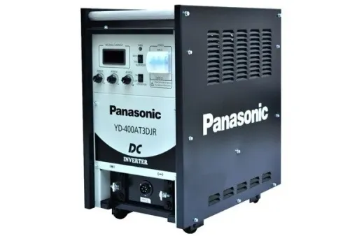
 | MAG Welding Machines Panasonic MAG Welding Machines Brand Panasonic Model YD-350GZ4 Phase 3-Phase Current 350 A Voltage 380-415 V Dimension (L x B x H) 380x550x640 mm Product Type New Duty Cycle 60%... View product → |
Frequently asked questions
What automotive parts suit submerged arc welding?
SAW suits thick automotive assemblies with long, straight or accessible seams, such as heavy frames, chassis members and structural components. It is a poor fit for thin body panels and short, difficult-to-reach joints.
How does a production SAW cell check the weld?
A SAW cell controls wire feed, current, voltage, travel speed and flux delivery, then checks factors such as seam tracking, flux coverage, bead shape, penetration and weld defects through the plant’s inspection process.
How does SAW compare with MIG, TIG, spot and laser welding?
SAW offers high deposition and deep, consistent welds on long, thick seams. MIG handles more varied joint positions, TIG provides precise lower-speed welding, spot welding suits overlapping sheet metal, and laser welding suits precise high-speed joints with tighter fit-up control.
How do you specify a Panasonic SAW system for an automotive plant?
Define the material, thickness, joint design, seam length, welding position, access, production rate, automation, wire and flux combination, inspection method, power-source capacity and service requirements before selecting the system.