
An inverter welding power source does more than reduce the size of a transformer: it converts, switches, transforms and regulates electrical energy fast enough to keep a manual arc stable. By the end, you will be able to trace the current from the incoming supply to the weld pool, set up the machine correctly, and judge whether its output, duty cycle and installation suit your job.
Key takeaways
- Rectifiers and capacitors create the DC link that feeds high-frequency switching.
- Set electrode polarity according to the electrode manufacturer’s instructions and welding procedure.
- Calculate duty cycle before sustained welding to prevent thermal shutdown and output loss.
- Check supply voltage, connections, cooling and fault codes when arc performance changes.
What happens inside the inverter power source
Incoming AC first passes through rectifier diodes, becoming pulsating DC. Capacitors smooth it into a DC link, which feeds IGBT transistors that switch the power on and off at high frequency. This switching waveform drives a compact high-frequency transformer, reducing voltage and providing isolation without the bulk of a mains-frequency transformer.
The conversion follows four stages:
- Rectification: incoming AC becomes DC.
- Inversion: IGBTs chop the DC at high frequency.
- Transformation: the transformer reduces voltage and transfers power.
- Output rectification: secondary-side devices convert the output back to DC, while inductors and capacitors smooth it.
Control electronics continuously measure current and voltage, then adjust IGBT switching to maintain the selected output. Protection circuits respond to overcurrent, overheating, short circuits and input faults. The arc is not produced directly by the high-frequency switching waveform; the electrode receives controlled, smoothed welding DC.
For MMA, the arc welding machine operates mainly as a constant-current source. You set amperage, while voltage changes with arc length. Open-circuit voltage helps ionise the gap when you touch and lift or scratch the electrode.
A long arc raises voltage and increases spatter and porosity risk; an overly short arc lowers voltage and can make the electrode stick or extinguish.
Compact size does not remove supply limits. Low line voltage, input surge, an undersized extension cord or a poorly regulated generator can trip the machine or reduce real output.
From power-on to arc extinction: the complete welding cycle
The arc welding machine working process starts with a safe electrical path: power source, electrode holder, electrode, arc, workpiece and return lead. The operator selects the electrode and polarity, clamps the return lead to clean metal, and sets the current within the electrode manufacturer’s range.
1. Inspect the machine, cables, holder and work clamp. Confirm the supply, protective earth and connections before switching on.
2. Switch on the supply. The machine presents open-circuit voltage at the electrode, ready to ionize the air gap without delivering full welding current.
3. Touch the electrode to the workpiece and lift it slightly, or scratch it across the surface. The gap ionizes, creating the arc and closing the welding circuit.
4. Hold a steady arc length. In constant-current SMAW, the set amperage remains the main control while arc voltage changes with length; a long arc increases spatter and porosity risk, while a short arc causes sticking or extinction.
5. Move at a controlled travel angle and speed. The arc melts the electrode and parent metal, while the flux coating produces shielding gas and a slag cover over the solidifying weld pool.
6. Reduce travel speed or pause briefly to fill the crater, then withdraw the electrode to extinguish the arc. Let the weld cool in still air, and remove slag only after solidification; disturbing it too soon can damage the bead or cause burns.
Practical setup, polarity and electrode control
A stable MMA arc starts with the correct electrode, polarity, current and cable connections. Follow these arc welding machine operation steps before and during the weld:
- Inspect the electrode holder, work lead, return clamp and insulation for damage. Confirm the machine’s input voltage, phase and protective earth match the site supply.
- Select the electrode diameter and classification for the joint. Connect DCEP or DCEN exactly as the electrode manufacturer specifies; the wrong polarity changes penetration, deposition and arc behaviour.
- Clamp the return lead to clean, bare base metal close to the weld. Remove paint, rust, oil and loose scale from the connection area.
- Set amperage within the electrode’s printed range. Use hot start to assist ignition and arc force to reduce sticking, but excessive values can increase spatter and undercut.
- Strike by touching and lifting or scratching the electrode, then hold an arc length close to the electrode core diameter. A long arc causes spatter and porosity; a short arc causes sticking and an irregular bead.
- Drag the electrode about 10 to 15 degrees from vertical, keep travel speed steady, and pause slightly at each edge. Stop forward movement before the pool becomes too wide.
- Chip and wire-brush slag between passes. At the end, fill the crater by briefly returning over it, then withdraw safely and let the weld cool.
E6013 electrodes commonly run on AC, DCEP or DCEN, while E7018 and stainless electrodes have narrower polarity and storage requirements. Use the packet’s amperage range rather than a generic setting. Inspect for cracks, undercut, porosity and incomplete fusion.
Duty cycle, installation and faults that affect real output
A 60% duty-cycle rating means six minutes of welding in a ten-minute period, followed by four minutes of cooling, at the manufacturer’s stated current and test temperature. It is a thermal limit, not a promise of uninterrupted output.
Restricted airflow, blocked vents, conductive dust and high ambient temperature heat the inverter faster, so reduce current or extend the cooling pause.
Before replacing power semiconductors, check the installation and the machine’s basic outputs:
- Confirm the input voltage, phase arrangement and supply frequency match the nameplate.
- Test the generator or extension supply for voltage drop during striking; long, undersized cords and poor regulation can cause nuisance trips.
- Confirm the cooling fan runs and air passages are clear.
- Inspect electrode-holder jaws, return-clamp contact and cable insulation.
- Tighten output terminals and check cable continuity.
- Read the fault code, then measure open-circuit output with a qualified technician.
Welding leads need sufficient cross-sectional area and the shortest practical route. Excess resistance reduces arc voltage, increases cable heating and makes a machine appear weak. Clamp the work lead to clean, sound metal close to the joint; paint, rust and loose connections create unstable current paths.
Protective earthing and dry gloves remain necessary even when a voltage-reduction device lowers open-circuit voltage. VRD settings must still suit the electrode and striking method.
Where DC inverter welding fits in an industrial process
Choose an inverter DC ARC machine for arc welding machine industrial use when the work moves between locations, the supply comes from a generator, or SMAW electrodes must cover repairs, structures and maintenance. Its portability and electrode flexibility outweigh slower deposition on short, varied welds.
| Option | Practical choice | Use something else when |
|---|---|---|
| DC inverter SMAW | Field repair, structural joints, maintenance and changing materials or positions | Long, repetitive welds make electrode changes and slag removal costly |
| MIG/MAG | Production welds, long seams and higher deposition with continuous wire | Wind, poor access or frequent site moves make shielding-gas control difficult |
| TIG | Clean, controlled welds on thin sections, stainless steel and critical root work | Speed and deposition matter more than finish; TIG is too slow |
| AC welding | Arc-blow problems on magnetised steel, or a process that specifically requires AC | You need DC polarity control, or aluminium AC TIG without an AC-capable machine |
Make the selection in this order:
- Match the joint, material, thickness and position to a qualified procedure, then identify whether SMAW, MIG/MAG, TIG or AC is specified.
- Check actual input voltage, phase, generator capacity, extension-cord size, duty cycle and site protection before trusting the nameplate output.
- Ask Weld Tech Corporation to compare a trial weld, suitable consumables, machine controls, repair support and rental availability rather than comparing amperage alone.
- Reject the machine if it lacks the required polarity, wire-feeding, gas, AC or automation function; nominal current cannot compensate for a missing process.
Related products
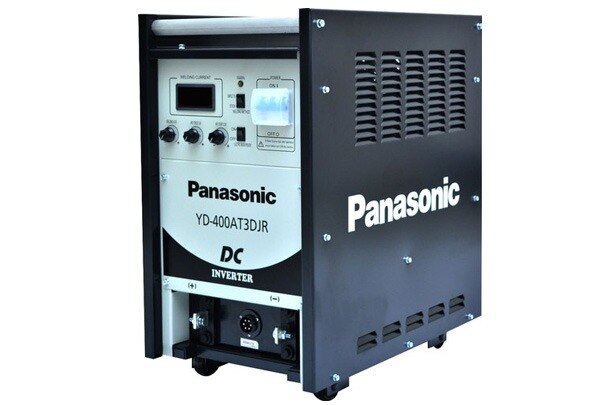
 | DC ARC Welding machine Inverter Controlled DC ARC Welding MODEL YD-400AT3 DJR INPUT SUPPLY 415 + - 20% PHASE / FREQUENCY THREE / 50-60 HZ POWER CONSUMPTION 17.6 KVA/16.7 KW WELDING CURRENT RANGE 20-400AMP... View product → |
 | MAG Welding Machines Panasonic MAG Welding Machines Brand Panasonic Model YD-350GZ4 Phase 3-Phase Current 350 A Voltage 380-415 V Dimension (L x B x H) 380x550x640 mm Product Type New Duty Cycle 60%... View product → |
Frequently asked questions
How does an inverter DC arc welding machine convert incoming power?
Rectifier diodes convert incoming AC into pulsating DC, capacitors smooth it into a DC link, and IGBT transistors switch it at high frequency before a compact transformer changes the voltage.
What are the main arc welding machine operation steps?
Power on the machine, select output settings and polarity, strike and control the arc, maintain electrode angle and arc length, then stop the arc and allow the machine to cool within its duty cycle.
How do polarity and electrode choice affect DC arc welding?
Connect the electrode holder and work return according to the electrode manufacturer’s instructions and the welding procedure, because polarity changes heat distribution, penetration and electrode behaviour.
What faults can reduce an inverter welding machine’s real output?
Incorrect supply voltage, loose cables, poor work-return contact, blocked cooling airflow, excessive duty-cycle demand and fault protection can reduce output or stop welding.