
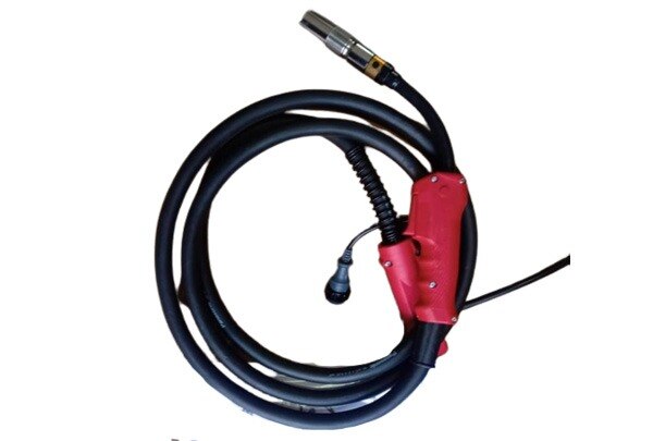
A plasma torch and a MIG torch consume replaceable parts for completely different jobs: one controls a high-temperature cutting jet, while the other feeds wire and shields a welding arc. By the end, you will be able to select each consumable set, verify compatibility, specify the torch for fabrication, and recognise wear before it causes poor cuts or unstable welds.
Key takeaways
- Match plasma electrodes, nozzles and swirl rings to the torch model.
- Inspect plasma parts for pitting, distortion, blocked orifices and cracking.
- Specify MIG torch duty cycle, wire size, connector, liner and shielding-gas needs.
- Verify every replacement by manufacturer part number, fit and application rating.
What each torch consumable actually does
A plasma torch’s consumables carry current and control a high-temperature gas jet; MIG torch parts feed wire and protect a weld pool. That is the key plasma cutting consumables and mig torch comparison: a plasma failure can distort the cut or extinguish the arc, while a MIG failure usually causes feeding, current-transfer or shielding-gas faults.
| Part | Function | Replacement logic |
|---|---|---|
| Plasma electrode | Carries cutting current and erodes at its emitting end | Replace when the pit reaches the torch maker’s limit |
| Plasma nozzle | Constricts the arc and shapes the cutting jet | Replace for a damaged or enlarged orifice |
| Swirl ring | Spins plasma gas around the electrode | Replace if cracked, blocked or heat-damaged |
| Shield and retaining cap | Protect the nozzle and hold the stack in position | Match them to shielded or unshielded operation |
| MIG contact tip | Transfers welding current to the wire | Replace when the bore enlarges, wire sticks or arc stability falls |
| MIG liner | Guides wire from the connector to the tip | Replace for drag, bird-nesting or inconsistent feeding |
| MIG diffuser | Seats the tip and distributes shielding gas | Replace for damaged threads, leaks or blocked passages |
| MIG gas nozzle | Directs gas around the arc and provides access to the joint | Clean spatter; replace distortion or restricted flow |
Plasma parts work as a matched stack: model, amperage and operating mode matter, so do not mix visually similar shields or nozzles. MIG parts are more modular; you often replace the worn tip, liner or nozzle without replacing the entire torch.
How to select and inspect a plasma consumable stack
Choose the complete stack from the power-source cut chart, not from the nozzle’s outside diameter. Material and thickness set the required amperage, gas, nozzle orifice and cutting speed; a nozzle rated for the machine’s maximum current can still produce a poor cut on thin sheet.
- Identify the torch model, revision and power-source software or cut-chart version. Confirm the approved electrode, nozzle, swirl ring, retaining cap, shield or standoff, because a part that fits can still have the wrong gas path or arc-start rating.
- Match the process: hand cutting, mechanized cutting, gouging or marking. Mechanized and gouging stacks can use different shields, stand-off distances and current ranges from a hand-cutting stack.
- Select the gas configuration. Clean, dry compressed air needs filtration and correct pressure; oil, water or unstable flow damages the electrode and distorts the jet. Oxygen, nitrogen and shop air also produce different cut quality and consumable life.
- Set the stack to the chart’s amperage for the material and thickness. Do not compensate for an oversized orifice by raising current; the arc can widen, pierce poorly or destroy the nozzle.
- Inspect before fitting. Replace an electrode with a deep central pit, a nozzle with a chipped or elongated orifice, a cracked swirl ring, a damaged shield or a retaining cap with heat damage. Keep the parts as a matched plasma cutting consumables selection, not a collection of interchangeable wear parts.
How to specify MIG torch requirements for fabrication
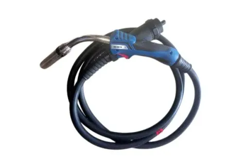
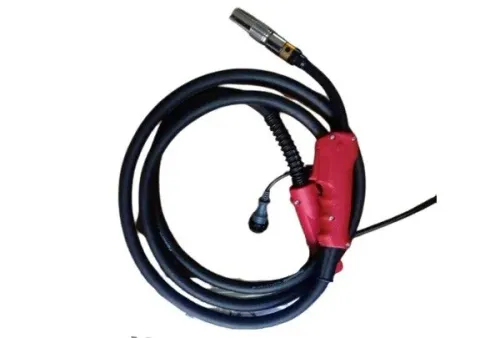
Confirm the wire, current, connection, access and gas before choosing a MIG torch; these are the essential torch requirements for fabrication. A torch rated only by maximum amperage can still feed poorly, overheat or fail to connect to the power source.
Check these specifications with the machine and welding process:
- Electrical: rated current at the stated duty cycle, welding polarity, trigger and control wiring, and the machine’s Euro or proprietary connector.
- Mechanical: torch length, neck shape, access clearance, cable routing, strain relief, and connector or adaptor type. A mechanically similar gun is unsuitable if its liner path, gas passage, power connection or control pins differ.
- Feeding: actual wire diameter and wire type, liner material and length, drive-roll compatibility, contact-tip bore, and required consumable part numbers. Aluminum wire needs a dedicated liner and feeding arrangement; a tight tip causes drag and burnback, while excess clearance produces erratic current transfer.
- Gas: shielding-gas type, regulator capacity, flow range, diffuser and nozzle design, and access around the joint. Confirm the required flow at the torch, not only the regulator’s maximum rating.
Air-cooled and water-cooled designs involve different installation requirements:
| Option | What to confirm | Main trade-off |
|---|---|---|
| Air-cooled | Rated duty cycle, ambient heat and cable length | Simpler setup, lower sustained-load capacity |
| Water-cooled | Cooler, pump, hoses, fittings and leak control | Higher sustained-load capacity, greater maintenance |
Choose consumables as a matched system: the liner guides wire, the contact tip transfers current, the diffuser distributes gas, and the nozzle shapes shielding coverage.
How to verify part numbers, fit and replacement quality
Confirm cutting consumable compatibility by matching the complete torch-and-power-source record, not by checking whether a nozzle physically fits. A plasma stack normally includes an electrode, nozzle, swirl ring, retaining cap and, on shielded torches, a shield; the torch revision, amperage, gas arrangement, operating mode and control-software or cut-chart revision must agree.
- Read the identification stamped on the torch and power source, then record the torch model, revision, rated amperage, gas type and hand, mechanised, gouging or marking mode.
- Compare every proposed part number with the manufacturer’s parts chart for that exact configuration. Confirm the electrode emitter, nozzle orifice, swirl-ring ports, shield and retaining-cap geometry; a wrong gas path or current rating can produce unstable arcs even when the parts assemble.
- Inspect the old electrode. Replace it when the hafnium insert has a deep or uneven pit, and replace the nozzle when its orifice is enlarged, oval or heat-damaged. Check compressed air for water, oil and particles before blaming the parts.
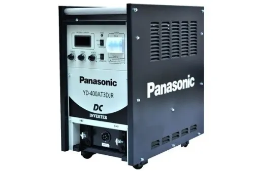
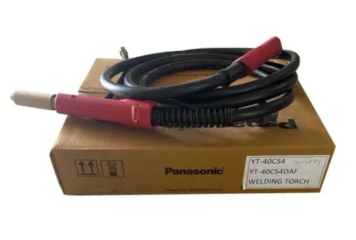
- For a MIG torch, verify the liner route, gas passage, power connection and trigger wiring alongside the connector. A Euro plug does not prove that the torch suits a Panasonic machine; ask Weld Tech Corporation to confirm the machine-specific adaptor or torch part number.
| Genuine | Exact maker specification, traceability and published fit | Critical amperage, gas-path or warranty requirements |
|---|---|---|
| Compatible | Aftermarket part matched to the stated torch and rating | A documented equivalent offers acceptable value |
| Generic | Broadly labelled part with uncertain geometry or materials | Avoid when identification, arc stability or cut quality matters |
Related products
 | MIG Welding Torch We are Manufacturer, Distributor, Supplier of MIG Welding Torches, MIG Welding Torch View product → |
 | MIG Welding Torch We are Manufacturer, Distributor, Supplier of MIG Welding Torches, MIG Welding Torch View product → |
How setup, duty cycle and wear determine the right replacement
Replace by the failed function, not by the headline amperage. Plasma and MIG duty-cycle figures describe different tests: plasma ratings use defined cutting current, input voltage and ambient temperature; MIG ratings depend on welding current, wire process, shielding gas and contact-tip-to-work distance.
| System | Operating limit | Wear diagnosis | Correct replacement test |
|---|---|---|---|
| Plasma stack | Torch revision, amperage, gas, mode and cut-chart software | Wide kerf, dross, misfire or unstable arc; inspect electrode pit, nozzle orifice and swirl ring | Match the complete stack: electrode, nozzle, swirl ring, retaining cap, shield or standoff |
| MIG torch | Rated current, air- or water-cooling, wire diameter, gas and duty cycle | Burnback, bird-nesting, feeding drag or porosity; inspect contact tip, liner, diffuser and nozzle | Confirm tip, liner length and material, torch curvature, connector and drive-roll setup |
For plasma cutting consumables, cutting consumable compatibility includes the gas path and arc-start characteristics, not just dimensions. Shielded parts are not substitutes for unshielded parts: the shield permits closer standoff and limits spatter reaching the nozzle.
Replace a damaged nozzle only after checking the electrode and swirl ring; a contaminated air supply or incorrect amperage can damage the new part.
For MIG wear, run the correct test before replacing parts:
- If feeding is erratic, check cable kinks, inlet contamination and drive-roll pressure before fitting a liner.
- If the tip is fused to the wire, check burnback settings and tip size before changing the torch.
- If porosity appears, check gas flow, nozzle blockage and leaks before blaming the diffuser.
That is the practical plasma cutting consumables and MIG torch comparison: match the replacement to the fault and operating setup, not appearance.
Frequently asked questions
What does each plasma torch consumable do?
The electrode carries current, the nozzle constricts the plasma jet, the swirl ring directs gas flow, and the shield cap protects and positions the cutting stack.
How do you select plasma cutting consumables?
Match the electrode, nozzle, swirl ring, shield cap and retaining cap to the torch model, material, amperage and cutting mode listed by the manufacturer.
What torch requirements matter for MIG fabrication?
Specify welding current and duty cycle, wire diameter, torch neck style, liner material and length, contact-tip thread, connector, trigger arrangement and shielding-gas flow.
How can you verify cutting consumable compatibility?
Compare the supplier’s exact part number with the torch manual, inspect dimensions and threads, and confirm the consumable is rated for your amperage and process.
When should you replace plasma or MIG torch parts?
Replace plasma parts when the orifice is enlarged, pitted or distorted, and replace MIG parts when feeding becomes erratic, the liner is contaminated, or the contact tip binds or burns back.
Related products
 | MIG Welding Wires Brand Panasonic Usage / Application MS Welding Thickness 0.8 mm Wire Material Copper / Copper Alloy Grade ER70S-6 Yield Strength Greater-than or... View product → |
 | Mig Torch We are Manufacturer, Distributor, Supplier of MIG Welding Torches, MIG Welding Torch View product → |