
Industrial MAG welding depends on more than pressing a torch trigger: the power source, wire feeder, gas circuit, work return, consumables and programmed functions must operate as one system. By the end, you will be able to follow the welding sequence, choose sensible starting parameters, interpret common faults and judge whether a machine setup suits your workshop.
Key takeaways
- Active gas shielding separates MAG welding from inert-gas MIG welding.
- Wire speed controls deposition and strongly affects welding current.
- Match voltage, gas flow and travel speed to the joint and material.
- Check duty cycle, wire path, torch parts and controls before production.
What happens inside a Panasonic MAG welding system?
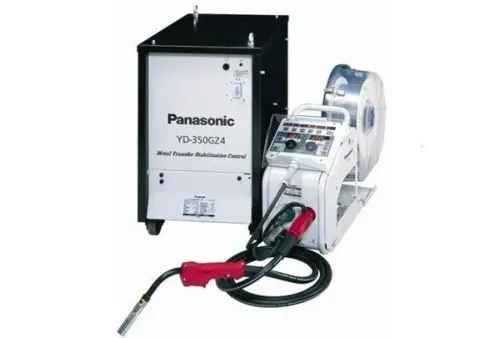
A Panasonic MAG system feeds a continuously moving solid wire electrode through the torch. The wire carries welding current, melts into the joint and forms an arc against the workpiece; active shielding gas protects the molten pool from air. Argon–CO₂ or argon–O₂ makes this MAG, while inert argon shielding makes it MIG.
The operating circuit and gas path involve these parts:
- The power source supplies controlled DCEP output: the wire is positive and the work-return clamp is negative.
- The wire feeder pushes the spool wire through the liner and contact tip, which transfers current to the electrode.
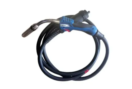
- The torch holds the tip and nozzle; the nozzle directs shielding gas around the arc but does not carry welding current.
- The clamp and return lead complete the electrical circuit through the workpiece.
- The regulator reduces cylinder pressure, while the solenoid valve starts and stops gas flow through the hose to the torch.
ISO 4063 calls solid-wire MAG process 135. Flux-cored MAG is process 136, even though both use active gas. Reversing DCEP changes penetration, spatter, arc stability and wire melting; it is not a harmless adjustment.
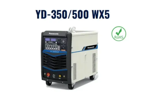
Choosing panasonic mag welding for machines means matching wire classification and diameter, gas, polarity, feeder, torch, liner and contact tip to the power source. That package determines whether panasonic mag welding remains stable in production.
How does the complete industrial MAG welding sequence work?
1. Start the mag welding machine operation by selecting the wire diameter, wire classification, shielding-gas program and polarity. Load the spool in the correct feed direction, match the drive rolls to the wire, and set pressure high enough to feed without slip but low enough to avoid deforming soft wire.
Thread the liner, inspect the contact tip and nozzle, open the regulator, and confirm gas delivery at the torch.
2. Use inching to advance wire without striking an arc. Use wire retraction to pull the electrode back for clearance or safe repositioning. Check the work-return clamp on clean metal before pressing the trigger.
3. Pressing the trigger opens the solenoid for pre-flow, advances the wire and establishes the arc. During welding, the feeder controls wire delivery while the power source maintains the selected arc voltage. Keep the torch position and travel speed consistent; controls cannot correct poor joint fit-up or a wrong welding program.
4. Releasing the trigger starts crater fill, burn-back and post-flow. Crater fill reduces end-crater cracking; burn-back prevents the wire freezing into the contact tip; post-flow shields the cooling weld pool and electrode end. Excessive burn-back fuses wire into the tip, while insufficient burn-back leaves excessive protruding wire.
After post-flow, close the regulator, shut down the machine and inspect the weld.
How do voltage, wire speed, gas and travel speed change the weld?
Wire speed, voltage, gas coverage and travel speed must be tuned as a coupled set in the industrial MAG welding process. In constant-voltage operation, increasing wire-feed speed raises welding current and deposition rate because more electrode must melt; reducing it lowers current. Voltage mainly changes arc length and bead width.
Slow travel increases heat input, penetration and bead size, but raises burn-through and distortion risk.
Electrical stick-out is the contact-tip-to-work distance. A longer distance preheats the wire through resistance, reducing penetration at the same settings; an excessively short distance raises current and can damage the contact tip. Follow the procedure’s specified distance.
| Transfer mode | Thickness and position | Main trade-off |
|---|---|---|
| Short-circuit | Thin material and out-of-position work | Lower heat input, but frequent short circuits and more spatter |
| Globular | Intermediate applications within its stable range | Less controlled arc and heavier spatter |
| Spray | Thicker material and suitable flat or horizontal work | Smooth, high deposition, but higher heat input; needs argon-rich gas |
| Pulsed spray | Thinner sections or positional work | Spray-like transfer with lower average heat input and less distortion |
Argon–CO₂ and argon–O₂ mixtures suit different programs; spray transfer needs an argon-rich mixture. Excessive flow creates turbulence and draws in air. Drafts, nozzle spatter, leaks, a blocked diffuser and a mispositioned torch then cause porosity. Verify flow at the torch, not only at the regulator, before changing Panasonic MAG welding settings.
Which starting settings suit common MAG welding jobs?
A starting chart is more useful than one “correct” setting. Use these ranges for a test bead, then confirm the wire manufacturer’s data sheet and approved WPS before production.
| Wire | Material and joint | Transfer | Wire speed | Voltage | Gas and flow | Starting stick-out |
|---|---|---|---|---|---|---|
| 0.8 mm solid | Thin mild-steel sheet; butt or lap | Short-circuit | 3.5–6.0 m/min | 17–20 V | Ar–CO₂ 82/18, 10–14 L/min | 10–12 mm |
| 1.0 mm solid | 2–4 mm mild steel; fillet or corner | Short-circuit | 4.0–7.0 m/min | 18–22 V | Ar–CO₂ 80/20, 12–16 L/min | 10–12 mm |
| 1.2 mm solid | 4–8 mm mild or higher-strength steel; butt or fillet | Short-circuit or pulsed | 4.5–8.0 m/min | 20–26 V | Ar–CO₂ 82/18, 14–18 L/min | 12–15 mm |
| 1.2 mm solid | Heavier plate; fillet or corner | Spray-capable | 7.0–11.0 m/min | 26–31 V | Ar–CO₂ 90/10, 16–20 L/min | 15–18 mm |
After the first bead, adjust one variable at a time:
- Increase wire speed when deposition is low.
- Correct voltage if the arc is too long or stubbing.
- Increase travel speed when the bead is too large.
- Stop increasing output when lack of fusion, undercut, burn-through or distortion appears.
In Panasonic mag welding machine operation, a synergic program is a linked starting curve for the selected wire, diameter and gas—not automatic approval of the finished weld. The industrial mag welding process still requires bead inspection and WPS compliance.
How do you diagnose faults and use duty cycle correctly?
Start at the gas cup and work backward when Panasonic MAG welding develops porosity, spatter, unstable feeding or poor penetration:
- Clean spatter from the nozzle, inspect the diffuser, and check that the torch gas passage is open.
- Measure gas flow at the torch while gas is flowing; do not trust the regulator setting alone. Test the hose for leaks and confirm that the solenoid opens.
- Inspect the contact tip and liner for wear, blockage, wrong size, sharp bends or excessive curvature.
- Confirm that the drive rolls match the wire. Too little pressure causes slip; too much pressure deforms wire. Keep wire away from oil, dust and condensation.
- Check the complete work-return path: clamp contact on clean metal, fixture connections, terminal tightness and leads without damage. A current path through painted fixtures or bearings can destabilise the arc.
- Confirm wire, gas and program settings, then make a test weld. Displayed voltage and current do not prove WPS compliance.
Duty cycle is the welding portion of a defined 10-minute test period. A 60% rating means six minutes welding at the stated output and four minutes cooling under manufacturer conditions—not six minutes at every setting or ambient temperature. Use the data plate, manual and IEC 60974-1 test context.
What must you check when selecting a Panasonic workshop or robotic setup?
Choose the cell before choosing the robot. A manual workshop needs accessible controls and a serviceable torch; a production line needs interface compatibility and repeatable programs; a TAWERS cell needs the power source, feeder, torch rating, cable dress, controller, software options, teach data and consumable geometry checked as one system.
| Setup | Check before purchase | Main risk |
|---|---|---|
| Manual cell | Feeder reach, torch cooling, liner access and operator controls | Poor feeding or excessive downtime |
| Production line | I/O interface, wire and gas programs, crater-fill, burn-back and service access | A program that cannot repeat across shifts |
| TAWERS robotic system | Controller, cable dress, teach data, software and Panasonic-specific torch package | Replacement parts that are not interchangeable |
TAWERS can synchronise robot movement, wire feed and arc functions more closely than a robot paired with a third-party welder. That improves control, but replacement planning becomes model-specific.
For panasonic mag welding for machines, compare cooling capacity, spare contact tips and liners, gas delivery, test-weld support and WPS documentation—not amperage alone. Confirm the complete industrial MAG welding process with a test weld.
Weld Tech Corporation in Hubballi can help check machines, torches, consumables, spare parts and gas-control equipment as a compatible package, not replace qualification testing.
Frequently asked questions
What happens inside a Panasonic MAG welding system?
A wire feeder pushes a solid electrode through the torch while the power source creates an arc. Argon-based active gas shields the molten weld pool from atmospheric contamination.
How does the complete industrial MAG welding sequence work?
The sequence starts with joint preparation and machine checks, then gas pre-flow, arc ignition, wire feeding, controlled travel, crater filling and post-flow. Inspect the finished weld after cooling.
How do voltage, wire speed, gas and travel speed change the weld?
Voltage changes arc length and bead shape, wire speed changes deposition and current, gas flow protects the pool, and travel speed changes bead size and penetration.
Which starting settings suit common MAG welding jobs?
Choose settings from the wire diameter, base-metal thickness, material, joint position and shielding-gas mix. Confirm the starting range in the Panasonic manual and qualify it on test welds.
How do you diagnose faults and use duty cycle correctly?
Trace porosity, spatter, burnback and unstable arcs through gas coverage, wire feeding, polarity, contact-tip condition, voltage and wire speed. Keep the machine within its rated welding time and cooling interval.